


HE220, HE260 HUMIDIFIER AND INSTALLATION KIT
69-1645EF 6
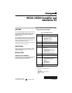
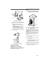
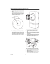
Fig. 12. Attaching sail to switch.
5. Press together the sides of the wire loop. Insert the
sail into the duct. (When in the Off position, the sail
should point into the direction of airflow as shown
in Fig.13.)
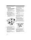
Fig. 13. Inserting sail switch in direction of airflow.
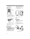
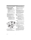
6. Secure the switch by using the sheet metal screws
provided.
7. After wiring, snap on the cover.
Installing the Humidistat
Installing on Mounting Duct
1. Apply the template to the duct location chosen
for the humidistat. Make sure the template is
level before drilling the holes.
2. Refer to the template (provided with the H8908
Humidistat Installation Instructions) to drill the
control assembly opening and mounting holes
for the H8908.
3. Remove the H8908 case from the base.
4. Position the foam gasket on the H8908 base.
5. Position the base on the duct with the arrow up.
6. Secure the base to the duct using the four
1 in. (25 mm) mounting screws provided with humi-
distat.
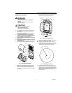
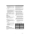
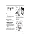
7. Connect the low-voltage wires to the leads and
replace the H8908 case. See Fig. 14.
NOTE: For wall mounting instructions, see the H8908
Installation Instructions.
Fig. 14. Humidistat base and rear view.
WIRING
CAUTION
Hazardous Voltage.
Can cause personal injury or equipment
damage.
Disconnect power supply before installing or
servicing equipment.
IMPORTANT
All wiring must comply with applicable local
code, ordinances and regulations.
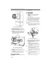
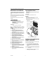
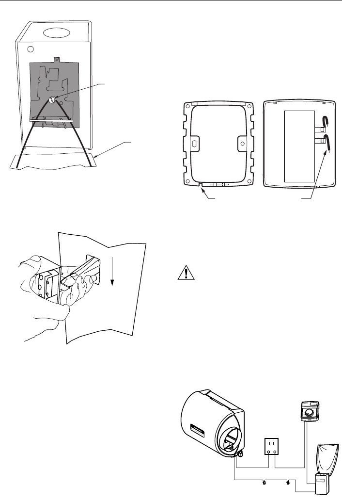
Wire the humidifier solenoid valve, sail switch, humidistat
and transformer. See Fig. 15.
Fig. 15. Wiring the controls.
– LOOSEN SETSCREW
– INSERT SAIL
– TIGHTEN SETSCREW
SAIL
M20181
M20178
AIRFLOW
M20179
WIRE SLOT
HUMIDISTAT WIRES
HUMIDISTAT BASE REAR OF HUMIDISTAT
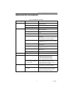
Humidity Control
Régulateur d'humidité
-20
¡F
-10 ¡F
0 ¡F
+10 ¡F
+20 ¡F
Over 20 ¡F
15%
20%
25%
30%
35%
40%
HUMIDITY
SETTING
OUT
DOOR
TEMPERATURE
-30
¡C
-25 ¡C
-20 ¡C
-10 ¡C
-5 ¡C
Over 0 ¡C
M20180
TRANSFORMER
BLACK
BLACK
BLACK
WHITE
WHITE
HUMIDIFIER
SOLENOID
VALVE
HUMIDISTAT
SAIL
SWITCH