


69-1104—3 2
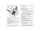
Fig. 2. Humidifier components.
5. Set the cabinet aside and drill the five 7/64 in. (3 mm) mount-
ing holes.
6. Start the three 3/4 in. (19 mm) sheet metal screws in the top
holes.
7. Place the humidifier housing over the screws, level the hous-
ing and tighten the three screws.
8. Use two 1/2 in. (13 mm) screws to secure the humidifier
housing at the bottom.
9. On the inside of the humidifier housing where the by-pass
tube connects, snap the bearing bracket in place with the U
shape of the bracket pointing up.
10. Snap the motor plate into place on the opposite side of the
humidifier housing.
NOTE: Be sure the motor coupling is positioned toward the top.
11. Place the lead wires through the hole in the bottom of the
motor cover and snap the cover in place.
12. Cut an opening for the 6 in. (152 mm) collar in the selected
by-pass location.
NOTE: Be sure to install a duct damper for summer shutoff if there
is air conditioning.
13. Install the 6 in. (152 mm) collar.
14. Use sheet metal screws to connect the by-pass tubing from
the collar to the humidifier.
15. Seal the connections with duct tape.
16. Insert the drain fitting in the bottom of the humidifier housing.
NOTE: Be sure the overflow tube is positioned toward the front,
on the same side as the by-pass tubing. The tubing should
not touch hot surfaces or sharp edges.
17. Place the water pan in the humidifier housing so the overflow
tube is above the previously installed drain fitting.
18. Attach a 3/8 in. (10 mm) I.D. tubing to the drain fitting and
route continuously downward to a suitable drain, or catch
basin.
19. Screw the float onto the float valve assembly.
20. Attach the float valve to the humidifier housing on the same
side as the motor.
21. Insert the valve hole plug in the double D hole on the oppo-
site side of the valve.
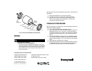
22. Assemble the drum and humidifier pad. See Fig. 3.
23. Insert the drum assembly into the motor coupling end and
snap into the bearing end.
24. Install the saddle valve (using the instructions on the saddle
valve bag) on the nearest cold water pipe.
25. Connect the copper tubing and route to the humidifier.
26. Connect the copper tubing to the humidifier valve and finger
tighten.
27. Use a 1/2 in. open end or adjustable wrench to tighten the
compression fitting securely.
28. Turn on the water at the saddle valve and adjust the water
level to 1-3/8 in. (35 mm) deep.
NOTE: To raise the water level in the water pan, turn the valve
adjustment screw (located on the water valve inside the
humidifier) clockwise to lower it and counterclockwise to
raise it.
M12252
WATER PAN
HUMIDIFIER
HOUSING
DRUM ASSEMBLY
BEARING END OF
DRUM SHAFT
COVER
WATER VALVE
OPENING