


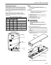

F300E ELECTRONIC AIR CLEANER
68-0240-1
9
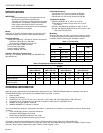
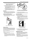
Select Wash Frequency
Use the W8600F DIP switches to program the time between
SERVICE indications. Be sure to select the setting according
to the conditions of the home. Factors to consider include the
duty cycle of the EAC, the number of people and pets, and
activities such as woodworking and other crafts that are being
done in the home.
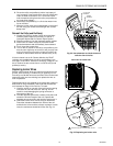
Refer to Table 4 to select the wash frequency. Set the
W8600F DIP switches to match the selection. See Fig. 10.
The time listed represents actual run time of the EAC, not
calendar days.
Table 4. Wash Frequency Options.
Wiring
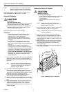
1. Run a 3-conductor thermostat cable (up to
18 gauge) from the W8600F to the terminal strip on
the air cleaner.
IMPORTANT
Connect cable to W8600F before attaching to the
air cleaner terminals to minimize the risk of
damage due to static electricity.
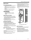
2. Connect the wires to terminals 1, 3 and 4 on the
W8600F. See Fig. 10.
3. Check that the battery is correctly installed in the
W8600F battery holder.
4. Snap the W8600F onto the base.
5. Turn off the power for the EAC.
WARNING
Electric Shock Hazard.
Can cause electrical shock or equipment
damage.
Disconnect EAC power and open the access door
before opening the power supply box cover.
6. Open the power supply box cover.
7. Remove the plug from the side of the power supply
box (plug can be a metal knockout or a blank terminal
strip).
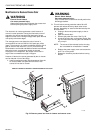
8. Install the terminal block/cable assembly supplied with
W8600F kit.
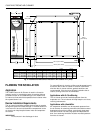
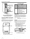
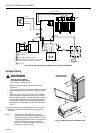
9. Plug the connector on the end of the cable assembly
into the J2 terminal on the driver board (included with
W8600F kit). See Fig. 11.
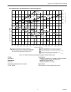
Fig. 10. Back of W8600F.
M11969A
BATTERY
IN HOLDER
DIP SWITCHES
RESET BUTTON
WIRING
TERMINALS (3)
BACK OF W8600F
1
3
4
1 2 3
UP
DIP Switch Settings
Wash Frequency
F1 F2 F3
(Days)
Off Off Off 10
Off Off On 20
Off On Off 30
Off On On 40
On Off Off 50
On Off On 70
On On Off 100
On On On 180
M14736
J2
J1
DRIVER
BOARD
TERMINAL
STRIP
MOUNTING
SCREW
POWER SUPPLY BOX
POWER SUPPLY
BOX COVER
POWER
SUPPLY
S
Y
S
T
E
M
Fig. 11. Installing the driver board on the EAC.