


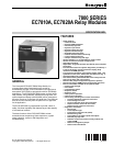


7800 SERIES EC7810A, EC7820A RELAY MODULES
3
66-2040
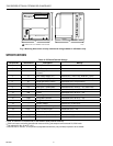
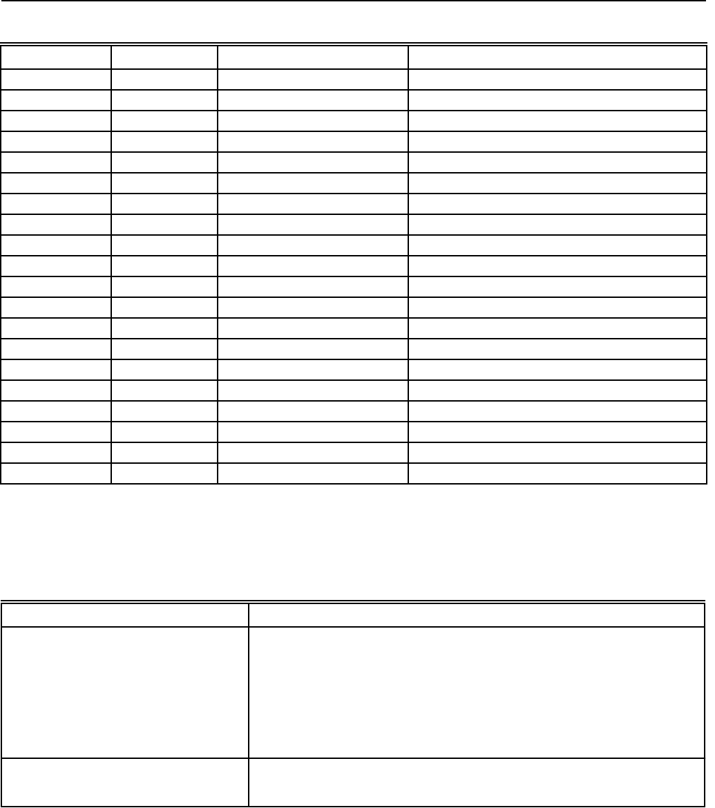
Table 1B. EC7820A Terminal Ratings.
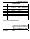
Table 2. Recommended grounding practices.
Ground type Recommended Practice
Earth ground (subbase and relay module). 1. Use to provide a connection between the subbase and the control panel of
the equipment. Earth ground must be capable of conducting enough current
to blow the 20A fuse (or breaker) in the event of an internal short circuit.
2. Use wide straps or brackets to provide minimum length, maximum surface
area ground conductors. If a leadwire must be used, use 14 AWG copper
wire.
3. Make sure that mechanically-tightened joints along the ground path are free
of nonconductive coatings and protected against corrosion on mating
surfaces.
Signal ground (KDM, Data ControlBus
Module™, Communications Interface
ControlBus™ Module).
Use the shield of the signal wire to ground the device to the signal ground
terminal 3(c) of each device. Connect the shield at both ends of the daisy chain
to earth ground.
a
See Table 2.
b
2000 VA maximum connected load to 7800 SERIES Relay Module Assembly.
c
Total load current, excluding burner/boiler motor and firing rate outputs cannot exceed 5A, 25A inrush.
d
Can also be 24 Vac, 3A at PF = 0.5.
e
220-240 Vac to 120 Vac, 10 VA (minimum) stepdown transformer (not provided) required to drive shutter.
Terminal No. Abbreviation Description Ratings
G Flame Sensor Ground
a
Earth G Earth Ground
a
N Line Voltage Common (Neutral)
3 AL Alarm (Normally Open) 220/230/240 Vac, 1A, 10A inrush for 5000 cycles.
4 FAN Burner/Blower Motor 220/230/240 Vac, 4A at P.F. = 0.5, 20A inrush.
5 L1 Line Voltage Supply (L1) 220-240 Vac (+10%/-15%), 50/60 Hz (±10%).
b
6 RT Limits and Burner Control 220/230/240 Vac, 5A (maximum).
7 LD2 Airflow Switch Input 220/230/240 Vac, 1 mA.
8 PV1 Pilot Valve 1 (interrupted) 220/230/240 Vac, 4A at P.F. = 0.5, 20A inrush.
c
9 MV Main Fuel Valve 220/230/240 Vac, 4A at P.F. = 0.5, 20A inrush.
c
10 IGN Ignition 220/230/240 Vac, 4A at P.F. = 0.2.
c
F(11) Flame Signal 135 to 220 Vac, current limited.
13 COM Firing Rate Common 220/230/240 Vac, 4A at P.F. = 0.5.
d
14 MOD Firing Rate Modulate 220/230/240 Vac, 4A at P.F. = 0.5.
d
16 Control Voltage 220-240 Vac (+10%/-15%).
17 ES2 Preignition Interlock Input 220/230/240 Vac, 1 mA.
18 ES1 Low Fire Switch Input 220/230/240 Vac, 1 mA.
20 LOS Lockout Input 220/230/240 Vac, 1 mA.
21 PV2 Pilot Valve 2 (Intermittent) 220/230/240 Vac, 4A at P.F.= 0.5, 20A inrush.
c
22 SHTR Shutter 220-240 Vac, 0.25A.
e