


2
7800 SERIES EC7810A, EC7820A RELAY MODULES
66-2040
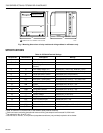
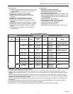
Fig. 1 Mounting dimensions of relay module and wiring subbase in millimeters only.
SPECIFICATIONS
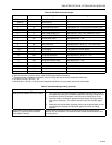
Table 1A. EC7810A Terminal Ratings.
127
127
BURNER CONTROL
133
M12821
1
REMOVE ONLY FOR TERMINAL TEST ACCESS.
1
a
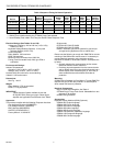
See Table 2.
b
2000 VA maximum connected load to 7800 SERIES Relay Module Assembly.
c
Total load current, excluding burner/boiler motor and firing rate outputs cannot exceed 5A, 25A inrush.
d
Can also be 24 Vac, 3A at PF = 0.5.
e
220-240 Vac to 120 Vac, 10 VA (minimum) stepdown transformer (not provided) required to drive shutter.
Terminal No. Abbreviation Description Ratings
G Flame Sensor Ground
a
Earth G Earth Ground
a
N Line Voltage Common
(Neutral)
3 L1 Line Voltage Supply (L1) 220-240 Vac (+10%/-15%), 50/60 Hz (±10%).
b
4 AL Alarm (Normally Open) 220/230/240 Vac, 1A, 10A inrush for 5000 cycles.
6 RT Limits and Burner Control 220/230/240 Vac, 5A (maximum).
7 LD2 Airflow Switch Input 220/230/240 Vac, 1 mA.
8 PV1 Pilot Valve 1 (interrupted) 220/230/240 Vac, 4A at PF = 0.5, 20A inrush.
c
9 MV Main Fuel Valve 220/230/240 Vac, 4A at PF = 0.5, 20A inrush.
c
10 IGN Ignition 220/230/240 Vac, 4A at PF = 0.2.
c
F(11) Flame Signal 136 to 220 Vac, current limited.
13 COM Firing Rate Common 220/230/240 Vac, 4A at PF = 0.5.
d
14 MOD Firing Rate Modulate 220/230/240 Vac, 4A at PF = 0.5.
d
16 Control Voltage 220-240 Vac (+10%/-15%).
17 ES2 Preignition Interlock Input 220/230/240 Vac, 1 mA.
18 ES1 Low Fire Switch Input 220/230/240 Vac, 1 mA.
20 LOS Lockout Input 220/230/240 Vac, 1 mA.
21 PV2 Pilot Valve 2 (Intermittent) 220/230/240 Vac, 4A at P.F.= 0.5, 20A inrush.
c
22 SHTR Shutter 220-240 Vac, 0.25A.
e