


3 69-0446—2
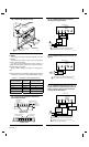
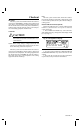
Fig. 7—CT8602C heating/cooling circuit in a two
transformer (one for heating, one for cooling)
system with gas heat and electric cooling, RC
and R terminals. Remove factory-installed R-RC
jumper.
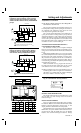
Setting and Adjustments
ADJUSTING CYCLE RATE
NOTE: MOST APPLICATIONS DO NOT REQUIRE A
CHANGE IN CYCLE RATE.
The room air temperature varies slightly from the com-
fort temperature setting with the cycling of the furnace or
air conditioner. The equipment cycles off and on as the
room temperature approaches the setpoint.
The cycle rate of this thermostat is set for heating at six
cycles per hour and for cooling at three cycles per hour as
shipped from the factory. The cooling cycle rate cannot be
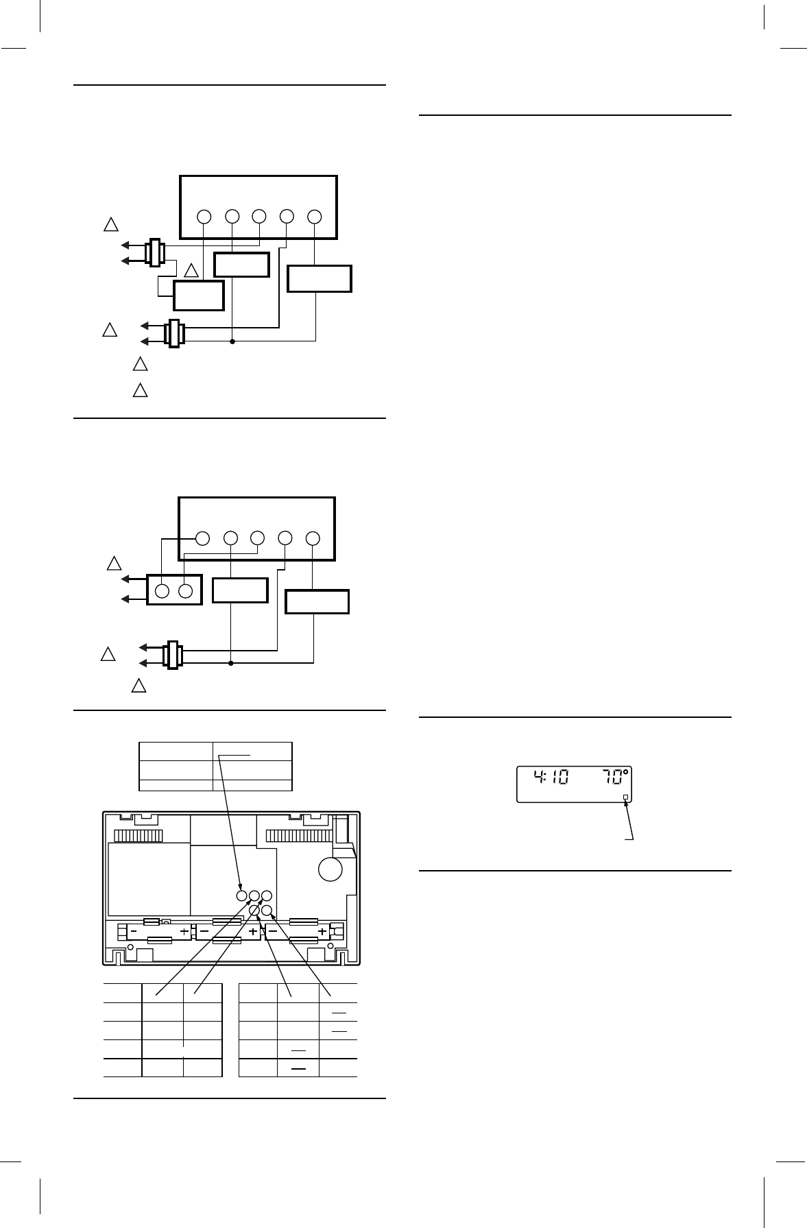
adjusted. The heating cycle rate can be adjusted by turning
one or both cycle rate adjustment screws located on the
back of the thermostat. See Fig. 9. Back out the screw about
one-half to one turn, or turn in until tight.
ADAPTIVE INTELLIGENT RECOVERY™/
CONVENTIONAL RECOVERY
The thermostat is factory-set for Adaptive Intelligent
Recovery™, but can be converted to conventional recovery
using screw 3A on the back of the thermostat as indicated in
Fig. 9.
With Adaptive Intelligent Recovery™, the room reaches
the comfort temperature at the exact time programmed into
the thermostat. The control temperature increases gradu-
ally, and turns the equipment on and off several times to
reach the comfort temperature slowly and on time. There is
no wasted energy associated with rapid temperature changes
and temperature overshoot.
With conventional recovery, program the start time to
be earlier than the desired comfort time. It may require
some trial and error to arrive at the best starting time.
NOTE: If you adjust screw 3A for conventional recovery, an
indicator appears in the lower right corner of the thermo-
stat display as a reminder that the Adaptive Intelligent
Recovery™ feature is not active. (Fig. 10).
Fig. 10—Conventional recovery indicator.
SETTING TIME/TEMPERATURE
The display readout can be converted between a 12 and
24 hour clock or °C and °F using screws 2A and 2B as
indicated in Fig. 9.
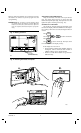
INSTALLING BATTERIES
Power is supplied for the thermostat by three AA alka-
line batteries. Batteries are included with thermostat. Install
batteries in back of thermostat as shown in Fig. 11. The
display will flash 1:00 PM and room temperature.
When the batteries are going dead, the display will flash
REPL BAT. Set system switch to OFF. Remove the ther-
mostat from the wall and install three new AA alkaline
batteries. We recommend Energizer
®
batteries. Change
L1
(
HOT
)
L2
1
2
1
2
Y
RCR
G
W
COOLING
CONTACTOR
24V
L1
(HOT)
L2
1
24V
M118
HEATING
PRIMARY
CONTROL
FAN RELAY
WALLPLATE
POWER SUPPLY. PROVIDE DISCONNECT MEANS
AND OVERLOAD PROTECTION AS REQUIRED.
PRIMARY CONTROL SUCH AS GAS VALVE OR
ELECTRONIC IGNITION MODULE.
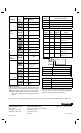
Fig. 8—CT8602C heating/cooling circuit in an oil
heating and electric cooling system. Heating
transformer is in oil primary, RC and R termi-
nals. Remove factory-installed R-RC jumper.
L2
L2
1
1
1
Y
RCR
G
W
TT
24V
M120
L1
(
HOT
)
L1
(
HOT
)
OIL PRIMARY
WALLPLATE
POWER SUPPLY. PROVIDE DISCONNECT MEANS
AND OVERLOAD PROTECTION AS REQUIRED.
COOLING
CONTACTOR
FAN RELAY
Fig. 9—Adjustments.
SYSTEM
GRAVITY
AIR/WATER
HOT
WATER
GAS/OIL
WARM AIR
ELECTRIC
WARM AIR
1A
OUT 1/2
TO 1 TURN
OUT 1/2
TO 1 TURN
OUT 1/2
TO 1 TURN
OUT 1/2
TO 1 TURN
1B
IN
IN
(FACTORY SETTING)
IN IN
TIME/TEMP
DISPLAY
2A 2B
24 HR IN
12 HR
o
o
C
F
OUT 1/2
TO 1 TURN
OUT 1/2
TO 1 TURN
IN
RECOVERY
SELECTION
ADAPTIVE
INTELLIGENT ™
CONVENTIONAL
3A
IN
(FACTORY SETTING)
OUT 1/2 TO 1 TURN
M8857
3A
1A
1B
2A 2B
PM
SET
PT
TUE
LEAVE
INDICATES
THERMOSTAT IS SET FOR
CONVENTIONAL RECOVERY
M8878