


69-0446—2 2
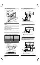
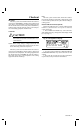
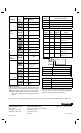
Fig. 2—Mounting wallplate on wall. Fig. 4—CT8602C heating-only circuit in a
continuous pilot gas system.
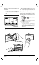
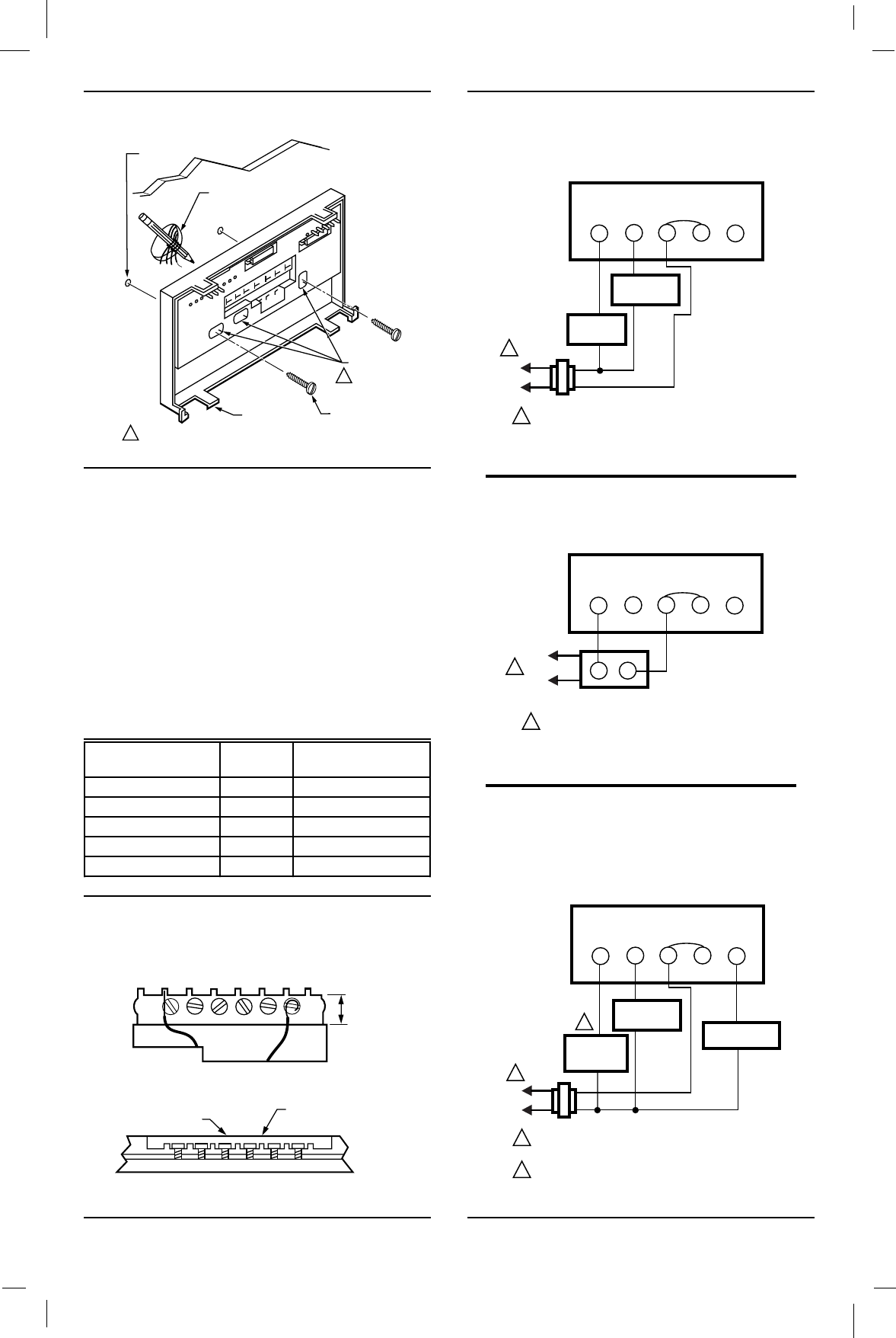
Fig. 6—CT8602C heating/cooling circuit in a
single transformer system with gas heat and
electric cooling or electric heat and electric
cooling, RC and R terminals.
L1
(HOT)
L2
1
1
Y
RCR
G
W
FAN RELAY
24V
WALLPLATE
M121A
FACTORY-
INSTALLED
JUMPER
GAS
VALVE
POWER SUPPLY. PROVIDE DISCONNECT MEANS
AND OVERLOAD PROTECTION AS REQUIRED.
Fig. 5—CT8602C heating-only circuit in an oil
system.
L1
(
HOT
)
L2
1
1
Y
RCR
G
W
TT
OIL PRIMARY
M122
WALLPLATE
POWER SUPPLY. PROVIDE DISCONNECT MEANS
AND OVERLOAD PROTECTION AS REQUIRED.
FACTORY-
INSTALLED
JUMPER
WIRES THROUGH
WALL OPENING
WALL
WALL
ANCHORS
(2)
WALLPLATE
MOUNTING
HOLES (3)
MOUNTING
SCREWS (2)
USE TWO MOUNTING HOLES THAT
BEST FIT APPLICATION.
1
1
M2917
WIRING
All wiring must comply with local electrical codes and
ordinances.
Disconnect power before wiring to prevent electrical
shock or equipment damage.
The shape of the terminal barrier permits insertion of
straight or conventional wraparound wiring connections.
Either method is acceptable.
Refer to Table 1 and Fig. 4 through 8 for wiring guide-
lines.
NOTE: Keep all wiring restricted to ribbed area surrounding
terminals (Fig. 3) to assure thermostat/wallplate contact.
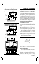
TABLE 1—TERMINAL CROSS REFERENCE.
FOR STRAIGHT
INSERTION –
STRIP 5/16 in. [8 mm]
FOR WRAPAROUND –
STRIP 7/16 in. [11 mm]
RESTRICT
WIRING TO
THIS AREA
WIRING TO BE BELOW
THIS SURFACE
TOP SURFACE
OF SUBBASE
FRONT VIEW OF
TERMINAL AREA
CROSS-SECTIONAL VIEW OF
TERMINAL AREA
M2927
Fig. 3—Keep wiring restricted to ribbed area
surrounding terminals.
Old Thermostat
Terminal Marked Function
New Thermostat
Terminal Marked
G or F Fan G
Y or C Cooling Y
W or H Heating W
RC, V, VC or R Power RC
RH, M, VR, 4 Power R
L2
1
2
2
1
Y
RCR
G
W
24V
M119
L1
(
HOT
)
COOLING
CONTACTOR
HEATING
PRIMARY
CONTROL
FAN RELAY
WALLPLATE
POWER SUPPLY. PROVIDE DISCONNECT MEANS
AND OVERLOAD PROTECTION AS REQUIRED.
PRIMARY CONTROL SUCH AS GAS VALVE OR
ELECTRONIC IGNITION MODULE.
FACTORY-
INSTALLED
JUMPER