


19 69-0733—3
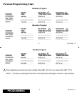
SYSTEM
GRAVITY
AIR/WATER
HOT
WATER
OR HIGH
EFFICIENCY
(90%+AFUE)
GAS/OIL
WARM AIR
ELECTRIC
WARM AIR
1A
OUT
1 TURN
OUT
1 TURN
OUT
1 TURN
1B
IN
(FACTORY SETTING)
IN IN
DISPLAY
2A 2B
12 hr./ °F
OUT
24 hr./ °F
(FACTORY SETTING)
IN
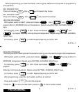
M 618A
1A
1B
2A 2B
OUT
OUT
OUT
IN
IN
IN
24 hr./ °C
12 hr./ °C
OUT
1 TURN
IN
BACK OF THERMOSTAT
3A
RECOVERY
SELECTION
3A
ADAPTIVE
INTELLIGENT
CONVENTIONAL
IN
(FACTORY SETTING)
TM
OUT
1 TURN
INSTALLATION
20 69-0733—3
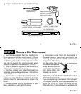
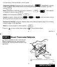
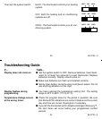
STEP 7
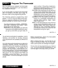
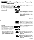
Adjust Fan Operation Switch, As Required
■■ The thermostat fan operation switch is fac-
tory-set in the left (NON ELEC) position. This is
the correct setting for most systems. If your
system is an electric furnace, set the switch to
the right (ELEC) position. The ELEC position
allows the fan to turn on immediately with the
heating or cooling system if the G terminal is
connected to a fan relay.
NOTE: Either the switch must be set before the
batteries are installed, or the left battery
must be removed to access the switch.
M619C
4A
FAN OPERATION SWITCH
(SHOWN IN NON ELEC POSITION)
BACK OF THERMOSTAT
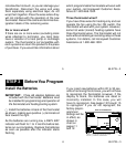
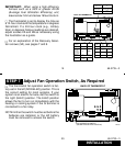
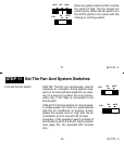
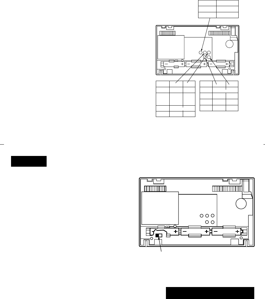
IMPORTANT:
When using a high efficiency
furnace such as a 90% or greater AFUE
(Average Fuel Utilization Efficiency) unit,
leave screw 1A in and screw 1B out one turn.
■■ The thermostat is set to display the time as
a 12-hour clock and the temperature in degrees
Fahrenheit. If a 24-hour clock (e.g., military
time) or degrees Celsius readings are desired,
adjust screws 2A and 2B as necessary using
the illustration as a guide.
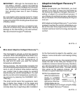
■■ For an explanation of the Recovery Selec-
tion screws (3A), see pages 7 and 8.