5 69-0333—6
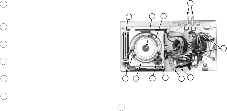
8 TEMPERATURE SETTING LEVERS.
Left (blue mark) controls the low tempera-
ture; right (red mark) controls the high
temperature.
9 PROGRAM PINS. Must be inserted into
24-hour timer dial slots to control program
index wheel.
10 PIN SLOTS. Located on 24-hour dial at
ten minute intervals for program pin
insertion.
11 HEAT ANTICIPATOR SCALE PLATE.
Calibrated to match the heating system
current draw in amperes.
12 ANTICIPATOR SETTING LEVER. Must be
adjusted to match the heating system
primary control current.
13 BULB AND BIMETAL ELEMENT (2).
Provides automatic temperature control by
switching the heating or cooling system on
and off.
5
4
8
13
14
9
10
7
6
12
11
M8749
14 AAA ALKALINE BATTERIES (2). Included
to provide power to the timer.


