


19 69-2245EF
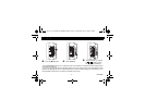
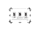
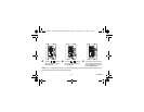
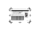
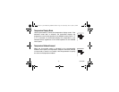
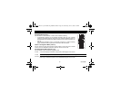
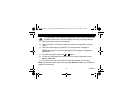
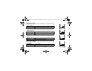
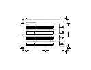
The configuration DIP switches are located on the back of the thermostat faceplate.
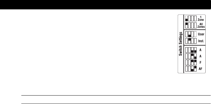
Scheduling Mode (switch 1)
Use DIP switch 1 to select between 1-ZONE and ALL-ZONES scheduling.
• All thermostats configured for ALL-ZONES scheduling share the same schedule
settings as the AQ2000 hydronic control panel. Any schedule modification made on a
thermostat will also be applied to the boiler controller and to the other thermostats (see
page 3).
• Any schedule modification made to a thermostat configured for 1-ZONE scheduling
applies to that thermostat only and does not affect the other thermostats.
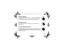
Installer’s Configuration Menu (switch 2)
Use DIP switch 2 to place the thermostat in either Installer or User mode. Set to Installer
mode to access the installation parameters. Otherwise, leave it in User mode.
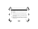
A/F/AF Regulation Mode (switches 3 & 4)
Use DIP switches 3 and 4 to select the regulation mode.
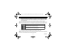
Configuration switches
A mode: controls and displays the Ambient air temperature. AIR will appear on the screen.
F mode: controls and displays the Floor temperature using an external sensor.
FLOOR will appear on the screen.
AF mode: controls and displays the Ambient air temperature while maintaining the Floor temperature within desired
limits using an external temperature sensor.
AIR/FLOOR will appear on the screen.
400-146-001-A_69-2245EF (AQ1000TP2) ENG.fm Page 19 Wednesday, June 18, 2008 2:32 PM