


18 69-2245EF
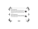
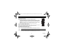
1.
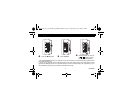
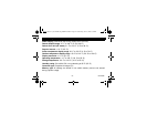
Remove the thermostat from its wallplate by unscrewing the screw underneath the thermostat
and tilting the bottom of the thermostat up. Note that the screw remains captive on the wallplate.
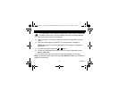
2. Insert the wires through the center hole of the wallplate and secure the wallplate to the wall or
onto an electrical box.
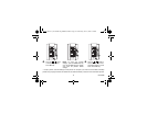
3. Connect the wires to the terminals on the thermostat’s wallplate (no polarity to observe).
NOTE: The recommended maximum wire length between the thermostat and the AQ2000 control
panel will vary according to the wire size. For example, for 22 AWG, use a maximum of 500 ft (150 m).
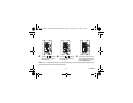
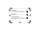
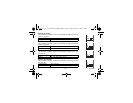
4. If necessary, set the configuration switches (see page 19).
5. Re-install the faceplate to the wallplate and secure with the captive screw.
NOTE: For optimal comfort control in the zone, keep the thermostat's air vents clean and unobstructed
at all times to ensure adequate air flow through the thermostat.
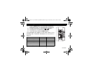
Installation
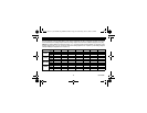
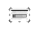
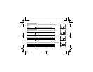
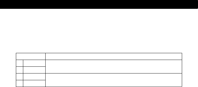
Terminal Description
1TH
AQ2000 Series hydronic control panel connections
2TH
3SENSOR
External sensor connections for floor temperature measurement (required only
if the thermostat is set to F or AF mode; see page 19)
4SENSOR
400-146-001-A_69-2245EF (AQ1000TP2) ENG.fm Page 18 Wednesday, June 18, 2008 2:32 PM