


4
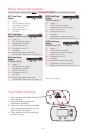
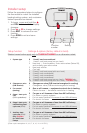
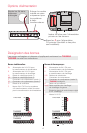
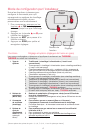
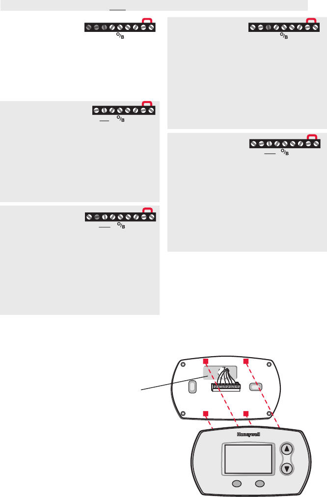
Thermostat mounting
1. Push excess wire back into the
wall opening.
2. Plug wall opening with non-
flammable insulation.
3. Align the 4 tabs on the wallplate
with corresponding slots on the
back of the thermostat.
4. Push gently until the thermostat
snaps in place.
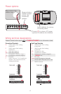
M29386
RcY
GR
C
M29381
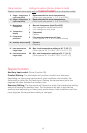
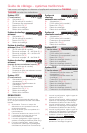
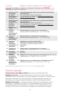
1H/1C Heat Pump
System
Rc Power [1]
R [R+Rc joined by jumper]
Y Compressor contactor
C 24VAC common [3]
O/B Changeover valve [7]
G Fan relay
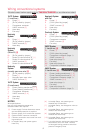
2H/1C Heat Pump
System (TH5220D only) [8]
Rc Power [1]
R [R+Rc joined by jumper]
Y Compressor contactor
C 24VAC common [3]
O/B Changeover valve [7]
G Fan relay
Aux/E Auxiliary/Emergency heat relay
L Sends output when set to Em. Heat [11]
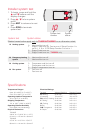
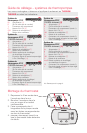
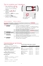
2H/1C Heat Pump
System
(TH5320U only) [8]
Rc Power [1]
R [R+Rc joined by jumper]
Y Compressor contactor
C 24VAC common [3]
O/B Changeover valve [7]
G Fan relay
Aux/E Auxiliary/Emergency heat relay
L Sends output when set to Em. Heat [11]
2H/2C Heat Pump
System
(TH5320U only) [9]
Rc Power [1]
R [R+Rc joined by jumper]
Y Compressor contactor (stage 1)
C 24VAC common [3]
O/B Changeover valve [7]
G Fan relay
Y2 Compressor contactor (stage 2)
L Sends output when set to Em. Heat [11]
3H/2C Heat Pump
System
(TH5320U only) [10]
Rc Power [1]
R [R+Rc joined by jumper]
Y Compressor contactor (stage 1)
C 24VAC common [3]
O/B Changeover valve [7]
G Fan relay
Aux/E Auxiliary/Emergency heat relay
Y2 Compressor contactor (stage 2)
L Sends output when set to Em. Heat [11]
See Notes on page 3.
RcYGAux
E
LR
C
RcYGAux
E
LR
C
RcYGY2
LR
C
RcYGAux
E
LR
C
Y2
Wiring heat pump systems
Shaded areas below apply only to TH5320U/TH5220D or as otherwise noted.