


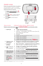
3
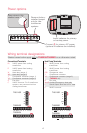
Wiring conventional systems
Shaded areas below apply only to TH5320U/TH5220D or as otherwise noted.
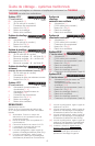
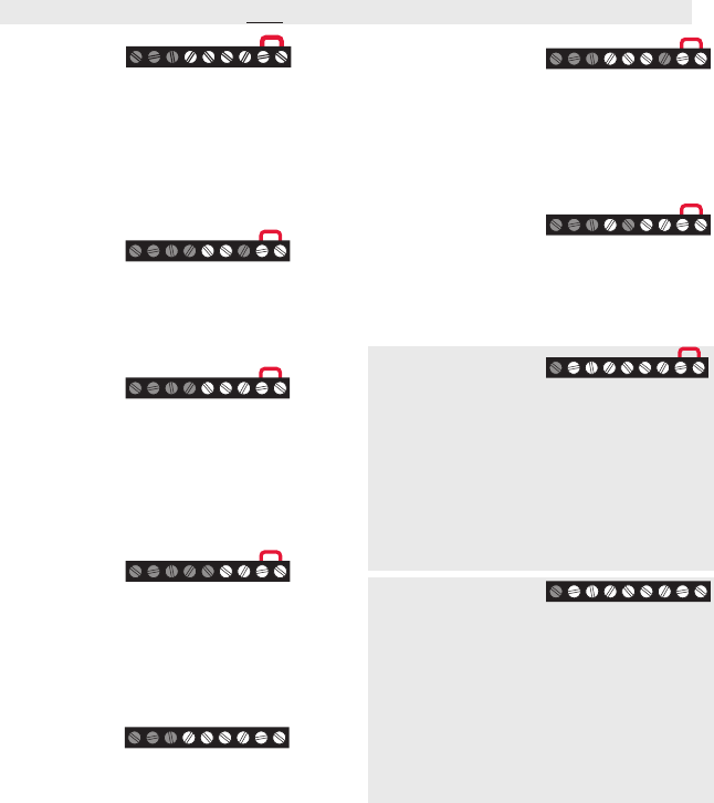
1H/1C System
(1 transformer)
Rc Power [1]
R [R+Rc joined by jumper]
Y Compressor contactor
C 24VAC common [3]
W Heat relay
G Fan relay
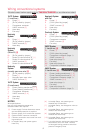
Heat-only
System
Rc Power [1]
R [R+Rc joined by jumper]
C 24VAC common [3]
W Heat relay
Heat-only
System
(Series 20) [5]
Rc [R+Rc joined by jumper]
R Series 20 valve terminal “R” [1]
Y Series 20 valve terminal “W”
C 24VAC common [3]
W Series 20 valve terminal “B”
Heat-only
System
(normally open zone valve) [5]
Rc [R+Rc joined by jumper]
R Power [1]
Y Normally open zone valve
C 24VAC common [3]
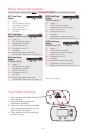
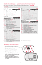
1H/1C System
(2 transformers)
Rc Power (cooling transformer) [1, 2]
R Power (heating transformer) [1, 2]
Y Compressor contactor
C 24VAC common [3, 4]
W Heat relay
G Fan relay
Heat-only System
with Fan
Rc Power [1]
R [R+Rc joined by jumper]
C 24VAC common [3]
W Heat relay
G Fan relay
Cool-only System
Rc Power [1]
R [R+Rc joined by jumper]
Y Compressor contactor
C 24VAC common [3]
G Fan relay
2H/2C System
(1 transformer) [6]
Rc Power [1]
R [R+Rc joined by jumper]
Y Compressor contactor (stage 1)
C 24VAC common [3]
W Heat relay (stage 1)
G Fan relay
W2 Heat relay (stage 2)
Y2 Compressor contactor (stage 2)
2H/2C System
(2 transformers) [6]
Rc Power (cooling transformer) [1, 2]
R Power (heating transformer) [1, 2]
Y Compressor contactor (stage 1)
C 24VAC common [3, 4]
W Heat relay (stage 1)
G Fan relay
W2 Heat relay (stage 2)
Y2 Compressor contactor (stage 2)
RcYWGRC
M29372
RcWRC
M29373
RcY
WR
C
M29374
RcYRC
M29375
RcYWG RC
M29376
RcWG RC
M29377
RcYG RC
M29378
RcYWGW2Y2 RC
M29379
RcYWGW2Y2 RC
M29380
NOTES
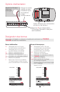
Wire specifications:
Use 18- to 22-gauge thermostat wire.
Shielded cable is not required.
[1] Power supply. Provide disconnect means
and overload protection as required.
[2] Remove jumper for 2-transformer systems.
[3] Optional 24VAC common connection.
[4] Common connection must come from cool-
ing transformer.
[5] In Installer Setup, set system type to
Heat Only.
[6] In Installer Setup, set system type to
2Heat/2Cool Conventional.
[7] In Installer Setup, set changeover valve to
O or B.
[8] In Installer Setup, set system type to
2Heat/1Cool Heat Pump.
[9] In Installer Setup, set system type to
2Heat/2Cool Heat Pump.
[10] In Installer Setup, set system type to
3Heat/2Cool Heat Pump.
[11] L terminal sends a continuous output when
thermostat is set to Em. Heat. Connect
to Honeywell zoning panels to switch the
panel to Emergency Heat.