


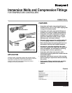

IMMERSION WELLS AND COMPRESSION FITTINGS
9 68-0040—04
WARNING
Electrical Shock Hazard or Equipment Damage
Hazard.
Can cause sever injury, death or short equipment
circuitry.
Disconnect all power supplies before installation.
Most equipment manufacturers provide a tapping for
temperature controller sensing element insertion. The tapping
should be located to measure average system temperature.
IMPORTANT
Always install the sensing element away from hot or
cold water inlets, steam coils, and locations where the
well pressure rating will be exceeded.
1. Turn off the power.
2. If the system is filled, drain it to a point below the boiler
tapping or sensing element location.
3. If no tapping is provided, prepare one, properly threaded,
at the desired location.
Immersion Well Mounting
Instructions for mounting the well in the tapping and using the
capillary mounting clamp or spring clip in remote bulb
applications follow. Consult the appropriate Aquastat®
Controller instructions for mounting the controller on the well in
direct insertion applications. Direct insertion applications
usually require using wells with a mounting flange on the spud.
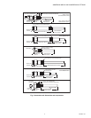
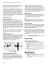
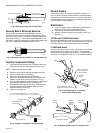
1. Coat threads with a moderate amount of pipe dope, leav-
ing two end threads bare. See Fig. 4.
NOTE: Teflon™ tape can also be used.
2. Screw the immersion well into the tapping and tighten
securely.
Fig. 4. Proper application of pipe dope.
Insert Sensing Bulb in Well
For good temperature response, the immersion well must fit
the sensing element or bulb tightly and rest against the bottom
of the well.
NOTE: If necessary, bend the tubing to hold the bulb against
the bottom of the well.
IMPORTANT
Any bends made in the piping must be gradual to pre-
vent breaks in the tubing and subsequent loss of fill.
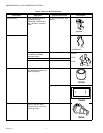
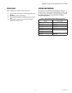
For faster heat transfer, use heat-conductive compound to fill
the space between the bulb and the well. A tube of
heat-conductive compound ships with Honeywell
TRADELINE® Aquastat Controllers. The compound is also
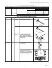
available as an accessory. See Table 5. Use the following
procedure when installing the compound:
1. Fill the well with compound.
2. Coat the bulb generously before inserting it into the well.
3. Move the bulb up and down inside the well to ensure
even distribution of compound.
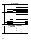
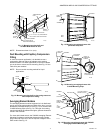
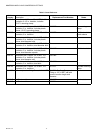
Securing Bulb with Mounting Clamp
Use the 121371 Mounting Clamp only on wells with a mounting
flange on the spud end.
1. Loosen the draw nut and spread the jaws of the clamp
with a screwdriver. See Fig. 5.
2. Slide the clamp jaws over the spud mounting flange
(point A in Fig. 5).
3. Adjust the tubing to fit through the mounting clamp
groove (point B in Fig. 5).
IMPORTANT
When tightening the draw nut, be careful not to
damage the capillary.
4. Tighten the draw nut so that the retainer clamp attaches
firmly to the well spud and holds the tubing securely in
place.
Fig. 5. Fastening bulb in well using mounting clamp.
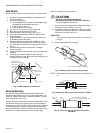
Securing Bulb with Spring Clip
The spring clip can be used with any well with the appropriately
size spud. Wells without a mounting flange on the spud require
a spring clip.
NOTE: The spring clip does not hold the capillary as securely
as does the mounting clamp. See Table 5 for spring
clip part numbers.
1. Slide the clip over the capillary with the prongs facing the
well.
2. Push the clip as far as possible into the spud. See Fig. 6.
NOTE: Make sure the bulb remains bottomed in the well.
APPLY A MODERATE AMOUNT
OF PIPE COMPOUND (LEAVE
TWO END THREADS BARE).
M17262
M8777
WELL
BULB
SPUD
MOUNTING
CLAMP
A
DRAW
NUT
TUBING
B
MOUNTING CLAMP
SCREWDRIVER
SPREAD JAWS
TO FIT OVER
RIDGE ON
WELL SPUD
JAWS