


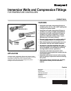
IMMERSION WELLS AND COMPRESSION FITTINGS
68-0040—04 12
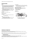
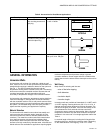
Bulb Shields
A bulb mounted outdoors requires protection of a bulb shield.
1. Expose the bulb to representative air temperature but
not direct sunlight.
2. Mount it high enough so:
a. Accumulated snow, leaves or other debris can-
not obstruct air circulation around it.
b. Children cannot reach it.
c. Avoid vents from the building.
3. Drill a 3/4 in. (19 mm) hole in the outside wall.
4. Bring the sensing bulb through the hole.
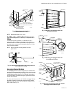
5. Mount the bulb in the bulb shield. See Fig. 16.
6. If the seal-off tube extends outside the shield, bend it
under the shield.
7. Hold the shield over the mounting location and form a
small-radius bend in the tubing.
8. Place the split plug (provided with 34886A; or order
107323A Split Plug separately) around the tubing and
move the bulb and shield into mounting position as a sin-
gle unit.
9. Push the split plug into the hole until it is wedged
securely in place.
10. Fasten the shield on the wall with screws (provided with
34886A).
11. If the tubing is properly shaped and the split plug
installed as directed, the shield covers the split plug and
conceals the hole in the wall.
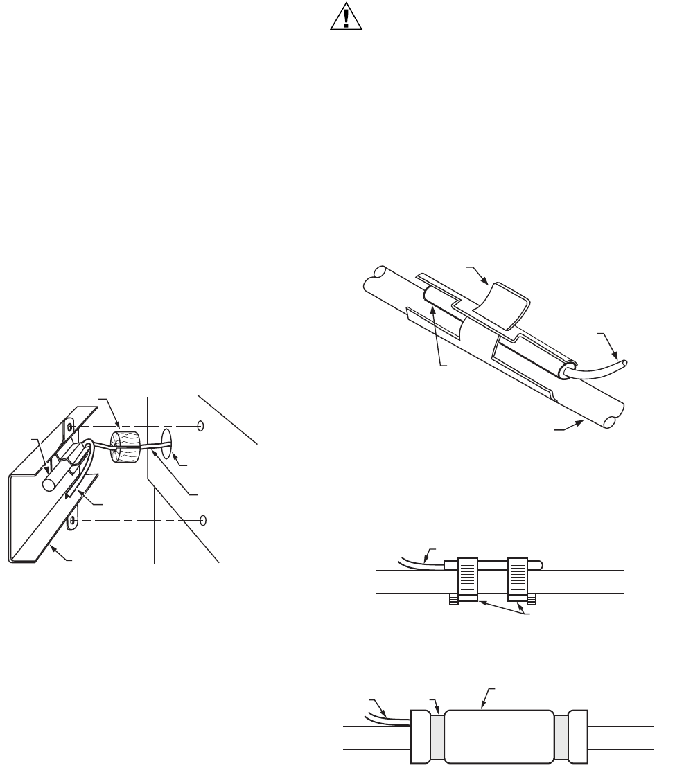
Fig. 16. Mounting bulb in bulb shield.
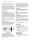
Strap-On Mounting
Occasionally, applications require the sensing bulb to be
strapped to the outside of a pipe. For these applications, use
either the 105900 Pipe Strap or metal hose clamps. The pipe
strap fits pipe up to 3/4 in. OD.
External mounting of the sensor produces a slight offset in the
temperature control point. Typically, the control temperature
increases as much as 5°F (2.8°C) with a bare sensor strapped
to the discharge pipe. Applying insulation around the sensor
and pipe decreases the offset. Insulation must be used if large
fluctuations in ambient temperature occur near the pipe.
Mount the bulb on the pipe as follows:
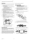
CAUTION
Significant Calibration Shift Hazard.
Overtightening clamps distorts bulb calibration.
Do not overtighten hose clamps.
1. Secure the bulb to the pipe with a 105900 Pipe Strap or
metal hose clamps. See Fig. 17 and 18.
2. If necessary, cover the bulb and pipe with foam rubber
insulation that extends at least 6 in. (152 mm) beyond
both ends of the bulb. See Fig. 19.
IMPORTANT
Do not allow the duct tape to come into contact with
the pipe.
3. Secure foam rubber with duct tape.
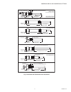
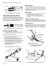
Fig. 17. Mounting bulb to pipe with pipe strap.
NOTE: When using a pipe strap, the maximum pipe OD is 3/4
in.
Fig. 18. Mounting bulb to pipe with metal hose clamps.
Fig. 19. Covering bulb and pipe with foam rubber
insulation.
M17272A
OUTDOOR
SENSING
BULB
EXTENSION
TUBE
BULB SHIELD
CAPILLARY
TUBING
3/4 IN. (19 mm)
HOLE IN WALL
PLUG HOLE WITH
ACCEPTABLE MATERIAL
BULB
T-CLAMP
CAPILLARY
TUBING
SUPPLY WATER PIPE
M8836
CAPILLARY TUBE
METAL HOSE CLAMPS
M17267
M17268
FOAM RUBBER WRAP (EXTEND
6 in. (152 mm) BEYOND ENDS OF BULB)
CAPILLARY
TUBE
PIPE
DUCT
TAPE