


21
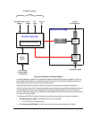
A built-in, SCADA-compatible report-back mechanism provides the status and alarm information.
This information is sent to the local PLC on site. The following signals are reported:
• OK state – signals that the oil drip rate exceeds a factory-set threshold. Whenever the oil drip
rate falls below this threshold, the OK state is disabled and a relay contact can turn off the well
pump directly or signal the SCADA room, which in turn can shut down the pump.
• Drip rate count– transmits the oil drip rate to the SCADA room, thereby providing the data to
calculate oil consumption.
• Lack of oil alarm – the Dripmaster detects and warns of a lack of lubrication, as a result of an
empty oil tank or blockage in the oil inlet or outlet.
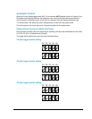
Manual operation is possible using the OPEN and CLOSE push buttons on the control panel. The
built-in peephole allows the operator to count the drips per minute.
Switching between the Pre-lube (pump off) mode and Normal (pump on) mode is accomplished by
applying or removing a 24 V AC/DC voltage to the S.B. terminals in the connection box. Applying a
24 V AC/DC voltage sets the Dripmaster to the Pre-lube mode of operation. Removing the 24 V
AC/DC voltage causes the Dripmaster to switch to the Normal (pump on) mode.
Search Feature
In exceptional cases, where only a few drops are counted, or none at all, the drip search function is
activated. This situation occurs if there is needle valve blockage or when there is a continuous flow
of oil. In the continuous flow case, there are no individual drops and consequently no counter
readings. Continuous oil flow may occur when filling an almost empty oil tank, for example. In case
of partial blockage, the drip search function scans until drops appear (the needle valve opens
continuously until drops are detected). If no drops are detected during the drip search (if the oil
blockage or continuous oil flow persists), then the needle valve eventually reaches its upper limit,
the UL LED illuminates briefly, and the motor changes its direction of rotation and starts to close the
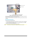
needle valve (Figure 10).
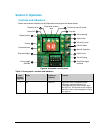
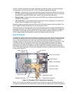
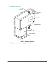
Internal solenoid
Manual oil flow switch
Overflow/vent hose
Photoelectric sensor
Drip verification peephole
Servo motor
Needle valve assembly
Upper Limit switch
Oil inlet
Oil outlet
Lower Limit switch
Control circuitry
interface
Figure 10: Dripmaster EDD-4C Needle Valve Assembly
When and if oil drops are detected, the search function stops, and normal stabilization resumes. If
no drops are detected while the needle valve is closing, then the needle valve eventually reaches its