7
Mounting behind a wall using discharge
extension (707U only)
1. Locate the inside wall template and mount on
inside wall. The inside wall opening must be cut
first. Be sure to follow the limitations noted as A,
B, and C printed on the template.
2. Check the template with a level to ensure proper
installation of the humidifier.
3. Drill (6) 5/16” diameter holes through the inside
wall only as shown on the template for mounting
the wire bracket on the wall using the anchor bolts
and flat washers provided. Drill a saw access hole
through the inside wall only in Area I as shown on
the template.
4. Cut out Area I of the inside wall using a saber saw
or equivalent. Do NOT cut out Area II at this time.
Do NOT cut through the entire wall as the
discharge hole on the other side of the wall will be
higher up.
5. Measure the thickness of the wall studs using the
cutout portion (Area I) on the template. This
measurement is used to drill a pilot hole for
locating the hole in the outside wall.
6. Drill (1) 1/4” pilot hole through the inside and
outside wall at the proper point in Area II on the
template. This will mark the proper center for the
discharge hole on the outside of the wall.
7. Cut out Area II of the inside wall using a saber saw
or equivalent. Do NOT cut through the entire wall.
8. Remove the template from the wall. In the (6)
5/16” diameter holes previously drilled into the
inside wall, install the (6) anchor bolts provided.
Remove each one of the bolts, and mount the wire
mounting bracket to the wall with (6) removed
bolts and flat washers.
9. The float and valve assembly have been factory
adjusted to maintain 1-1 1/2” of water in the water
reservoir pan at normal water pressure. If
necessary, bend the float arm to the required
position to maintain the water level at other water
pressures.
10. When installing the atomizing assembly into the
water reservoir pan, be sure that the drip tubes do
not interfere with the operation of the float and
valve assembly. Interference can be eliminated by
rotating the entire atomizing assembly within the
water reservoir pan.
Physical installation
NOTE:
The following items are located in
the carton:
• Bottom pan
• Extension discharge
nozzle
• Atomizing assembly
• Discharge dome (plastic)
• Wire mounting bracket
The following items are located in
the bag identified :
“707 TW Hardware Kit”:
• Inside wall template
• Outside wall template
• (6) anchor bolts
• (1) flexible connector sleeve
• (2) hose clamps
• (1) bezel
The following items are located in
the bag identified :
“707 SM/STD Hardware Kit”:
• (6) #10 flat washers
Inside wall
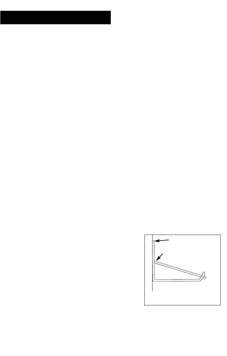
Wire mounting bracket
Bracket should be level


