


6
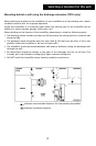
Mounting on the face of a vertical return duct
or side of a horizontal return
1. Mount the installation template on the side of the
cold air return air duct with the center line of the
template lined up with the center line of the return
air duct. The narrow side of the duct may be used if
space permits.
2. Check the template with a level to ensure proper
installation of the humidifier.
3. Drill (4) 1/8” diameter holes (as shown on the
template) for mounting the wire bracket with sheet
metal screws and flat washers provided.
4. Cut out the circle marked on the template. Do not cut
this opening undersized.
5. With a hammer and a heavy piece of metal,
straighten the metal edges to prevent injury to
yourself and damage to the humidifier.
6. Fit the rubber channel around the cut-out to cover
the rough edges of the hole and trim to fit.
7. Attach the wire mounting bracket to the duct with (4)
#10 sheet metal screws and flat washers (provided).
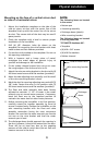
8. Move the side adjusting arms vertically until the shelf
of the wire mounting bracket is level.
9. Mark the duct for securing adjusting arms and drill (2)
1/8” holes. Fasten the arms in this position with (2)
#10 sheet metal screws and flat washers (provided).
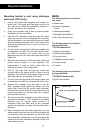
10. The float and valve assembly have been factory
adjusted to maintain 1-1 1/2” of water in the water
reservoir pan at normal water pressure. If necessary,
bend the float arm to the required position to
maintain the water level at other water pressures.
11. Before mounting the humidifier in its final position,
carefully rotate the impeller assembly by hand to
ensure it rotates freely. Position the humidifier on the
wire mounting bracket with the float and valve
assembly connection facing the most convenient
location. Be sure that the water reservoir pan feet do
not rest on the wire bracket and that the water
reservoir pan is level.
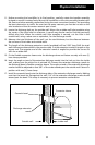
12. The discharge dome should approach the opening in
the duct, however, it should not extend into the duct.
There will be no heat loss, due to the negative
pressure of the cold air return duct (the air flow will
create a vacuum in the duct).
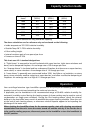
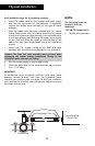
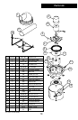
Physical installation
NOTE:
The following items are located
in the carton:
• Bottom pan
• Atomizing assembly
• Discharge dome (plastic)
• Wire mounting bracket
The following items are located
in the bag identified
“707 SM/STD Hardware Kit”:
• Template
• (6) #10 x 3/4” screws
• (6) #10 flat washers
• Rubber channel
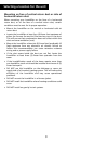
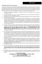
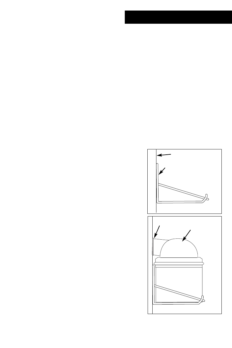
Cold air return duct
Wire mounting bracket
Bracket should be level
Rubber channel
Discharge
dome