


25Heatilator • Novus NNXT • 4055-879 • Rev. o • 2/12
H
1
V
1
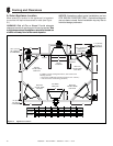
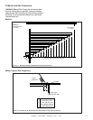
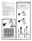
To replace the fi rst starter elbow with two 45° elbows,
refer to Figure 7.4. All other 90° elbows can be replaced
with two 45° elbows.
General Rules:
• SUBTRACT 3 ft. from the total H measurement for each
90° elbow installed horizontally.
• SUBTRACT 1-1/2 ft. from the total H measurement for
each 45° elbow installed horizontally.
• A maximum of three 90° elbows (or six 45° elbows)
may be used in any vent confi guration. Some elbows
may be installed horizontally. See Figure 7.8.
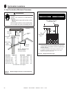
• Elbows may be placed back to back anywhere in the
system as long as the fi rst 90° elbow is a starter elbow
except as shown in Figure 7.4.
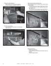
• When penetrating a combustible wall, a wall shield
fi restop must be installed.
• When penetrating a combustible ceiling, a ceiling
fi restop must be installed.
• Horizontal runs of vent do not require vertical rise;
horizontal runs may be level.
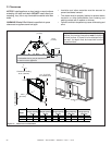
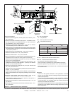
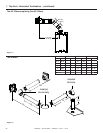
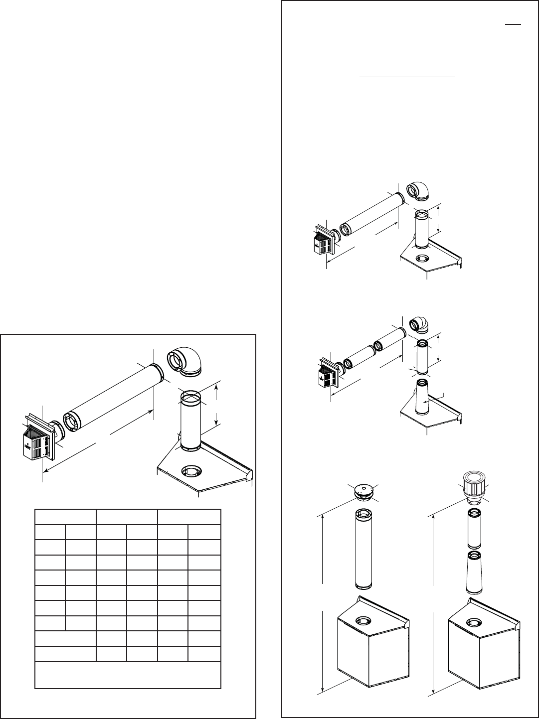
E. Vent Diagrams
Figure 7.3
One Elbow
1. Top Vent - Horizontal Termination
Note: The NNXT series appliances can adapt to
SLP series vent pipe when venting off the top of
the appliance. You must use a DVP-SLP24 adapter
which can only be attached to the appliance starting
collar.
When looking at horizontal termination diagrams, the
adapter is not counted as part of the minimum vertical
(V
1
min.) requirements.
Whether horizontal or vertical termination, the adapter is
counted as part of the maximum vertical limitations.
All venting rules for the vent run must still be followed.
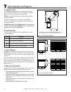
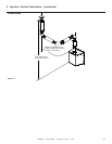
H
1
= 11 ft.
max.
V
1
= 1 ft.
DVP-SLP24
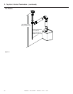
H
1
= 11 ft.
max
V
1
= 1 ft.
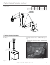
DVP
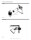
HORIZONTAL EXAMPLE
SLP
12 ft (3.66 m) min.
60 ft (18.29 m) max.
12 ft (3.66 m) min.
60 ft (18.29 m) max.
DVP
VERTICAL EXAMPLE
SLP
DVP-SLP24
Adapter
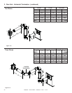
V1 min. V1 max. H1 max.
ft m ft m ft m
0 0.00 - - 2 0.61
0.33 0.10 - - 4 1.22
0.5 0.15 - - 6 1.83
1 0.30 - - 11 3.35
1.5 0.46 - - 17 5.18
2 0.61 - - 17 5.18
DVP 25 7.62 17 5.18
SLP 23 7.01 17 5.18
You may install the elbow directly on top
of the appliance (DVP only).