


11Heatilator • Novus NNXT • 4055-879 • Rev. o • 2/12
J. Before Lighting Fireplace
Before operating this fi replace for the fi rst time, have a
qualifi ed service technician:
• Verify all shipping materials have been removed from
inside and/or underneath the fi rebox.
• Review proper placement of logs, rockwool and/or other
decorative materials.
• Check the wiring.
• Check the air shutter adjustment.
• Ensure that there are no gas leaks.
• Ensure that the glass is sealed and in the proper position
and that the integral barrier is in place.
WARNING! Risk of Fire or Asphyxiation! DO NOT oper-
ate fi replace with fi xed glass assembly removed.
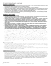
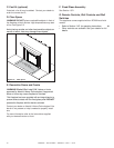
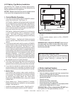
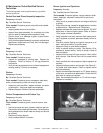
NG/LP SETTING
WIRE LEAD FROM REGULATOR CONNECTS HERE
MODULE
Figure 2.3 Control Module
H. IPI Battery Tray/Battery Installation
The IntelliFire Plus
TM
system has a battery backup option.
Battery longevity and performance will be affected by the
service temperatures of this appliance.
NOTICE:
Batteries should only be used as a power source
in the event of an emergency such as an outage.
I. Control Module Operation
1. The control module has an ON/OFF/REMOTE selector
switch that must be set. See Figure 2.3.
OFF Position: Appliance will ignore all power inputs and
will not respond to any commands from a wall switch or
remote. The unit should be in the OFF position during
installation, service, battery installation, fuel conversion,
and in the event that the control goes into LOCK-OUT
mode as a result of an error code.
ON Position: Appliance will ignite and run continuously
in the HI fl ame setting, with no adjustment in fl ame
output. This mode of operation is primarily used for
initial installation or power outage operation with battery
backup.
REMOTE Position: Appliance will initiate commands
from an optional wired wall switch and/or the wireless
remote.
2. If using a wired wall switch with the module in REMOTE
mode, the fl ame output can be adjusted with the HI/LO
selector switch on the module. See Figure 2.3. Note
that the fl ame HI/LO selector switch will become inactive
once an optional remote control is programmed to the
control module. Note that the control module will always
ignite the fi replace on HI and remain so for the initial 10
seconds of operation. If the HI/LO is switched to the
LO position, the fl ame output will automatically drop to
the lowest setting after the fl ame has been established
for 10 sec. After this 10 second period, the fl ame can
be adjusted from HI to LO with the switch.
3. The control module has safety feature that automatically
shuts down the fi replace after 9 hours of continuous
operation without receiving a command from the remote.
4. If you intend to use both an optional wired wall switch
and the remote control to operate your fi replace, the wall
switch will override any commands given by the remote.
5. Module Reset
This module may lock-out under certain conditions.
When this occurs, the appliance will not ignite or respond
to commands. The module will go into lock-out mode
by emitting three audible beeps, then continuously
displaying a RED/GREEN error code at its status
indicator LED.
• Check battery tray. Remove batteries if installed.
Batteries should only be installed for use during power
outages. See Section H.
• Locate the module selector switch. (See Figure 2.3).
• Set the module selector switch to the OFF position.
• Wait fi ve (5) minutes to allow possible accumulated gas
to clear.
• Set the module selector switch to ON or REMOTE
position.
• Start the appliance.
WARNING! Risk of Explosion! DO NOT press the mod-
ule reset switch more than one time within a fi ve minute
time period. Gas may accumulate in fi rebox. Call a quali-
fi ed service technician.
Nine Hour Safety Shutdown Feature
This appliance has a safety feature that automatically
shuts down the fi replace after 9 hours of continuous
operation without receiving a command from the
remote.