


Heatilator • Novus BV-Mesh • 4031-553 Rev F • 11/07 25
12
12
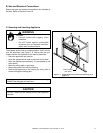
Appliance Setup
A. Remove the Shipping Materials
Remove shipping materials from inside or underneath the
fi rebox.
Shock Risk
Fire Risk
Use ONLY optional accessories approved
for this appliance.
• Using non-listed accessories voids
warranty.
• Using non-listed accessories may result
in a safety hazard.
• Only Hearth & Home Technologies
approved accessories may be used
safely.
WARNING
E. Clean the Appliance
Clean/vacuum any sawdust that may have accumulated in-
side the fi rebox or underneath in the control cavity.
B. Remove the Clean Face Components
Carefully remove skin pack from face of unit. Set aside.
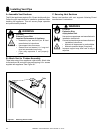
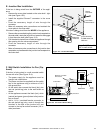
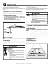
C. Remove Glass Assembly
• Pull the four (30/33/36 in. appliances) or seven (42 in.
appliance) glass assembly latches out of the groove on
the glass frame. See Figure 12.1.
• Remove the glass panel from the appliance.
• Lay aside out of the way on a non-abrasive surface.
D. Accessories
Install approved accessories per instructions included with
accessories. Refer to Section 16 for available optional ac-
cessories.
Explosion Risk
• Follow rockwool placement instructions
in this manual.
• Do NOT place rockwool directly over
burner ports.
• Replace rockwool material annually.
Improperly placed rockwool interferes with
proper burner operation.
WARNING
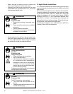
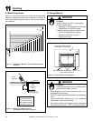
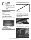
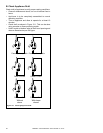
F. Lava Rock, Vermiculite, Rockwool Placement
See Figure 12.2 for placement location.
Placing the Rockwool
Rockwool is shipped with this gas appliance. To place the
rockwool:
• Place a small amount of 1/2 in. diameter pieces (dime-size)
of rockwool on the burner pan so that the rockwool touches
but does not cover the holes in the burner pan. This will
provide the “glowing embers” look. It is not necessary to
use the entire bag. Save the remaining rockwool for future
use.
Placing the Lava Rock
• See Figure 12.2.
Placing the Vermiculite
• Sprinkle on top of lava rock.
Lava Rock &
Vermiculite
Rockwool
Figure 12.2 Placement of Rockwool, Lava Rock and Vermiculite
Latches
(both bottom
and top)
Glass
Assembly
Figure 12.1 Glass Assembly