


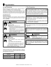

Heatilator • Novus BV-Mesh • 4031-553 Rev F • 11/07 23
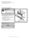
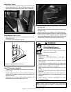
E. Junction Box Installation
If the box is being wired from the OUTSIDE of the appli-
ance:
• Remove the cover plate located on the outer shell - right
side (see Figure 10.3).
• Install the supplied Romex™ connector in the cover
plate.
• Feed the necessary length of wire through the
connector.
• Make all necessary wire connections and reattach the
cover plate to the outer shell.
If the box is being wired from the INSIDE of the appliance:
• Remove the screw attaching the junction box/receptacle to
the outer shell, rotate the junction box inward to disengage
it from the outer shell (see Figure 10.3).
• Pull the electrical wires from outside the appliance through
this opening into the valve compartment.
• Feed the necessary length of wire through the
connector.
• Make all necessary wire connections to the junction box/
receptacle and reassemble the junction box/receptacle to
the outer shell.
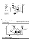
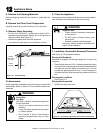
WHT
WHT
BLK
BLK
GRN wire
inside box
Copper
ground attached
to GRN screw with
GRN wire
14/2WG
Cover Plate
outside firebox
Romex
Connector
Figure 10.3 Junction Box Detail
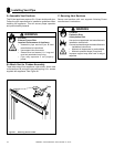
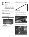
Note: Do NOT wire 110
VAC to wall switch.
Red
Switch
Switch Box
Red
Black
Black
Green
Green
White
Power
Supply
Wires
White
Red
Black
Green
White
Minimum 14-3 AWG
with Ground
Junction Box
Knockout
Figure 10.4 Fan Control Switch Wiring
F. Wall Switch Installation for Fan (Op-
tional)
If the box is being wired to a wall mounted switch
for use with a fan (See Figure 10.4):
• The power supply for the appliance must be
brought into a switch box.
• The power can then be supplied from the switch
box to the appliance using a minimum of 14-3
with ground wire.
• At the switch box connect the black (hot) wire
and red (switch leg) wire to the wall switch as
shown.
• At the appliance connect the black (hot), white
(neutral) and green (ground) wires to the junction
box as shown.
• Add a 1/4 in. insulated female connector to
the red (switch leg) wire, route it through the
knockout in the face of the junction box, and
connect to the top fan switch connector (1/4 in.
male) as shown.