


22 Heatilator • Novus BV-Mesh • 4031-553 Rev F • 11/07
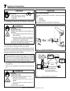
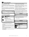
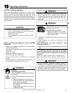
D. Standing Pilot Ignition System Wiring
• This standing pilot ignition system wiring does not require
a 110 VAC supply to operate.
Ignitor
Flame
Sensor
Pilot Assembly
GRN
ORG
BLK
ORG
Control
Box
To
Junction
Box
Battery
Pack
3V
Adaptor
BLK
BRN
RED
RED
BLK
BLU
Valve
Limit
Switch
WHT
+
-
+
-
Optional SPST
Wall Switch
OR
Optional Remote
WHT
GRN*
*
GRN wire only used with
optional wall switch
WSK-MLT-HTL
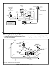
Figure 10.1 Intellifi re Pilot Ignition (IPI) Wiring Diagram
Pilot
Ignitor
GAS
VALVE
To Burner
Gas Inlet
Inlet Tap
ORG
TAN
Thermopile
WHT
RED
Flame Sensor
Copper
Tubing
Push
Button
Ignitor
Outlet Tap
Wall Switch (or
thermostat if
heater-listed)
WHT
RED
GRN wire only used with
optional wall switch
WSK-MLT-HTL
HIGH
LIMIT
SWITCH
BLU
BLU
BLK
BLK
Pilot Tube
WHT
Figure 10.2 Standing Pilot Ignition Wiring Diagram
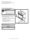
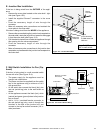
• It is recommended that a 110 VAC junction box be installed
for use with a fan or remote control. (See Figure 10.2 for a
wiring diagram and Figure 10.3 for junction box wiring.)
¨