


45Heatilator • GDST3831I • 2127-900 Rev. K • 7/12
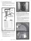
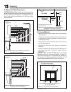
A. Mantel and Wall Projections
WARNING! Risk of Fire! Comply with all minimum clear-
ances as specifi ed. Framing closer than the minimums list-
ed must be constructed entirely of noncombustible materi-
als (i.e., steel studs, concrete board, etc.) Failure to comply
could cause fi re.
13
13
Finishing
Figure 13.3 Combustible Mantel Leg or Wall Projections
(Acceptable on both sides of opening)
Note: All
measurements
in inches.
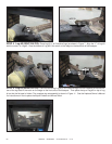
Note: Clearance from opening to
perpendicular wall.
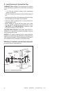
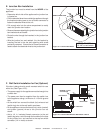
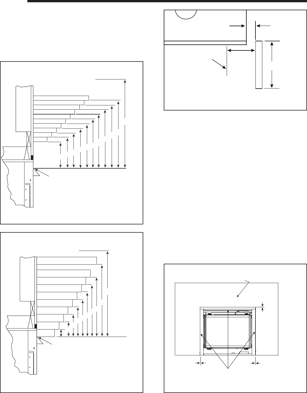
B. Facing Material
• Metal front faces may be covered with non-combustible
materials only.
• Facing and/or fi nishing materials must not interfere with
air fl ow through louvers, operation of louvers or doors,
or access for service.
• Facing and/or fi nishing materials must never overhang
into the glass opening.
• Observe all clearances when applying combustible
materials.
• Seal joints between the fi nished wall and appliance top
and sides using a 300 °F minimum sealant. Refer to
Figure 13.3.
WARNING! Risk of Fire! DO NOT apply combustible
materials beyond the minimum clearances. Comply with
all minimum clearances to combustibles as specifi ed in
this manual. Overlapping materials could ignite and will
interfere with proper operation of doors and louvers.
0 in.
0 in.
0 in.
Finish wall material may be
combustible - Top and Sides
High Temperature Sealant (300° F/149° C min.)
Top and Side Seal Joint
Figure 13.4 Noncombustible Facing Diagram
5
6
7
8
9
10
3
4
5
12
11
10
9
8
7
6
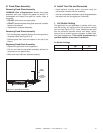
TOP OF HOOD OR FIREPLACE OPENING
MIN.
MAX.
4
12
13
11
32
CEILING
TOP VIEW
3-1/4 in.
Min.
1/2 in.
Min.
Unlimited
FIREPLACE
OPENING
Note: All
measurements
in inches.
5
6
7
8
14
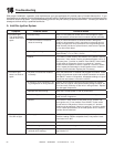
TOP OF HOOD OR FIREPLACE OPENING
MIN.
4
5
12
18
11
10
9
8
7
6
MAX.
2
3
1
32
CEILING
4
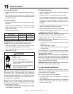
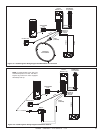
Figure 13.2 Minimum Vertical and Maximum Horizontal
Dimensions of Non-Combustibles
Figure 13.1 Minimum Vertical and Maximum Horizontal
Dimensions of Combustibles