


5
Unit Coolers
Condensate Drain Lines
Either copper or steel drain lines should be used and properly protected
from freezing. In running drain lines, provide a minimum 1/4 inch per
foot pitch for proper drainage. Drain lines should be at least as large
as the evaporator drain connection. All plumbing connections should
be made in accordance with local plumbing codes. All condensate
drain lines must be trapped, and run to an open drain. They must
never be connected directly to the sewer system. Traps in the drain
line must be located in a warm ambient. We recommend a trap on
each evaporator drain line prior to any tee connections. Traps located
outside, or extensive outside runs of drain line must be wrapped with
a drain line heater. The heater should be connected so that it operates
continuously. It is recommended that the drain line be insulated to
prevent heat loss. A heat input of 20 watts per linear foot of drain line
for 0˚F (-18˚C) room applications and 30 watts per linear foot for -20˚F
(-29˚C) rooms is satisfactory. In freezers, the evaporator drain pan tting
should be included when heating and insulating the drain line.
Inspect drain pan periodically to insure free drainage of condensate.
If drain pan contains standing water, check for proper installation. The
drain pan should be cleaned regularly with warm soapy water.
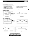
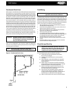
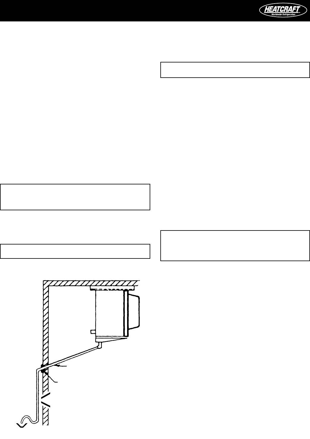
Figure 5. Condensate Drain Lines
DRAIN LINE MIN.
PITCH - 1/4”/ FT.
VAPOR SEAL
TRAP
OPEN
DRAIN
Traps on low temperature units must be outside of refrigerated
enclosures. Traps subject to freezing temperatures must be wrapped
with heat tape and insulated.
Field Wiring
The eld wiring should enter the areas as provided on the unit. The
wiring diagram for each unit is located on the inside of the electrical
panel door. All eld wiring should be done in a professional manner
and in accordance with all governing codes. Before operating unit,
double check all wiring connections, including the factory terminals.
Factory connections can vibrate loose during shipment.
1. The serial data tag on the unit is marked with the electrical
characteristic for wiring the unit.
2. Consult the wiring diagram in the unit cooler and in the con
-
densing unit for proper connections.
3. Wire type should be of copper conductor only and of the
proper size to handle the connected load.
4. The unit must be grounded.
5. For multiple evaporator systems, the defrost termination
controls should be wired in series. Follow the wiring diagrams
for multiple evaporator systems carefully. This will assure
complete defrost of all evaporators in the system.
6. Multiple evaporator systems should operate o of one ther
-
mostat.
7. If a remote defrost timer is to be used, the timer should be
located outside the refrigerated space.
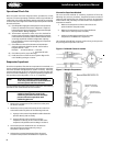
Check Out and Start Up
NOTE: All adjustable controls and valves must be eld
adjusted to meet desired operation. There are no
factory preset controls or valve adjustments. This
includes low pressure, high pressure, adjustable
head pressure systems and expansion valves.
After the installation has been completed, the following points should
be covered before the system is placed in operation:
(a) Check all electrical and refrigerant connections.
Be sure they are all tight.
(b) Check the room thermostat for normal operation
and adjust.
(c) Wiring diagrams, instruction bulletins, etc. attached
to the condensing units should be read and led for
future reference.
(d) All fan motors on evaporators should be checked for
proper rotation. Fan motor mounts should be carefully
checked for tightness and proper alignment.
(e) Electric and hot gas evaporator fan motors should
be temporarily wired for continuous operation until
the room temperature has stabilized.
(f) Do not leave unit unattended until the system has
reached normal operating conditions and the oil
charge has been properly adjusted to maintain the oil
level between 1/4 and bottom of the sight glass.
(g) Make sure all Schrader valve caps are in place and tight.
WARNING: All wiring must be done in accordance with
applicable codes and local ordinances.
WARNING: All power must be disconnected before clean-
ing. Drain pan also serves as cover of hazard
-
ous moving parts. Operation of unit without
drain pan constitutes a hazard.
NOTE: Always trap single evaporator system drain
lines individually to prevent humidity migration.