


4
Installation and Operations Manual
the area above the unit cooler must be sealed or exposed in such a way
to facilitate hand cleaning without the use of tools. When lagging or
bolting the unit ush to the ceiling, seal the joint between the top and
the ceiling with an NSF listed sealant and ends of open hanger channels
must be sealed to prevent accumulation of foreign matter.
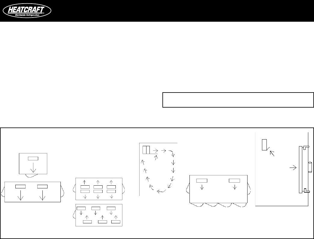
When locating unit coolers in a cooler or freezer, refer to Figures 1
through 4 for guidelines.
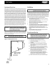
Unit Cooler Mounting
Most evaporators can be mounted with rod hangers, lag screws, or
bolts. Use 5/16" bolt and washers or rod for up to 250 pounds, 3/8"
for up to 600 pounds and 5/8" for over 600 pounds. Care should be
taken to mount the units level so that condensate drains properly.
Note that some unit cooler designs achieve drain pan slope by using
dierent height mounting brackets. In this situation, the top of the
mounting brackets should be level. Adequate support must be
provided to hold the weight of the unit.
When using rod hangers, allow adequate space between the top of
the unit and the ceiling for cleaning. To comply with NSF Standard 7,
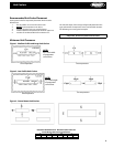
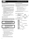
Figure 4. Large Coolers and Freezers Placement.
Elevation view of glass display
door cooler or freezer. Be sure
air discharge blows above, not
directly at doors. Provide bae if
door extends above blower level.
Glass
Display
Door
Bae
Where one wall evaporator
mounting is satisfactory.
Cooler or Freezers
where one wall will not
accommodate all required
evaporators or where air
throw distance must be
considered.
Baed Unit - Allow sucient
space between rear of Unit Cooler
and wall to permit free return of
air. Refer to Figures 1 through 3
(page 3) for proper space.
Cooler or Freezer with Glass
Display Doors
NOTE: Always avoid placement of Unit Coolers direct above
doors and door openings.
Defrost Troubleshooting
Fan Motor
If the motor does not operate or it cycles on thermal overload, remove
motor leads from terminal block and apply correct voltage across the
leads. If motor still does not operate satisfactorily, it must be replaced.
Before starting the unit, rotate fan blades to make sure they turn freely
and have sucient clearance.
Fan Delay & Defrost Termination Control
This control is a single pole double throw switch. The red lead wire
is wired to common. The black wire is wired in series with the fan
motors. The brown wire is wired in series with the defrost termination
solenoid in the timer. The brown and red contacts close and the black
and red contacts open when the temperature is above 55
º
F. The black
and red contacts close and the brown and red contacts open when
the temperature is below 35
º
F.
On initial “pull down” of a warm box the fan will not start until
the coil temperature reaches approximately 35
º
F. If the box is still
comparatively warm (60
º
F) when the fan starts, then blowing this
warm air over the coil may cause it to warm up to 55
º
F and thus stop
the fan. Therefore, the fan may recycle on initial “pull down.” This
control cannot be adjusted.
If the fan motor fails to start when the control is below 35
º
F, disconnect
the fan motor leads and check the motor as described for fan motors.
Also check whether current is being supplied at “N” and “4” from the
timer. The fan delay control must be below 35
º
F when checking for
a closed circuit.
Defrost Heater
If unit shows very little or no defrosting and does not heat, disconnect
heater and check to nd if it is burned out. To test, apply correct voltage
across heater or use continuity ashlight battery tester.
Drain Pan
If drain pan has an ice build-up, drain line may be frozen. The
drain line should be pitched sharply and exit cabinet as quickly as
possible. Sometimes location and ambient at the drain outside of
cabinet may cause freeze-up. A drain line heater may be required
to correct the freeze-up. Any traps in the drain line must be located
in a warm ambient.