


9
Heat & Glo • VRT-AUB • 2123-980 Rev. H • 5/12
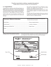
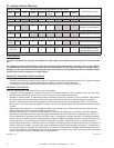
A. Appliance Certication
1
Listing and Code Approvals
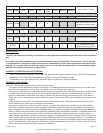
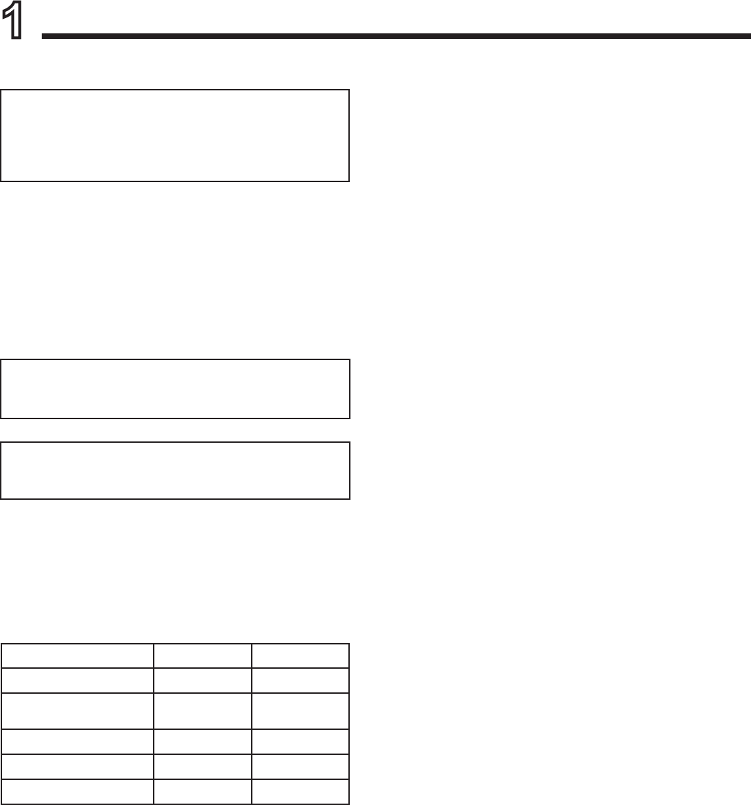
C. Gas Pressure Requirements
Pressure requirements for VRT-AUB replaces are shown
in table below.
Two taps are provided on the right hand side of the gas
control for a test gauge connection to measure the inlet
and outlet pressures.
MODELS: VRT-AUB
LABORATORY: SAI Global
TYPE: Gas Space Heating Appliance
STANDARD: AS4553:2008
D. High Altitude Installations
NOTICE: If the heating value of the gas has been reduced,
these rules do not apply. Check with your local gas utility
or authorities having jurisdiction.
When installing above 610 meter elevation:
Reduce input rate 4% for each 305 meters feet above
610 meters.
E. Non-Combustible Materials Specication
Material which will not ignite and burn. Such materials are
those consisting entirely of steel, iron, brick, tile, concrete,
slate, glass or plasters, or any combination thereof.
Materials that are reported as passing ASTM E 136,
Standard Test Method for Behavior of Materials in a
Vertical Tube Furnace at 750 ºC (1832 ºF) and UL763
shall be considered non-combustible materials.
F. Combustible Materials Specication
Materials made of or surfaced with wood, compressed pa-
per, plant bers, plastics, or other material that can ignite
and burn, whether ame proofed or not, or plastered or
unplastered shall be considered combustible materials.
G. Electrical Codes
All electrical safety testing has been done following the EN
60335-2-102 standard. Local codes apply.
The Heat & Glo gas appliances discussed in this Installer’s
Guide have been tested to certication standards and listed
by the applicable laboratories.
This appliance must be installed in accordance with the
rules in force.
NOX Class 5 for G20, NOX Class 5 for G31
B. Additional Related Standards
The installation must comply with these installation instruc-
tions and all relevant parts of Local and National Building
Standards Regulations and those relevant recommenda-
tions of the following British Standards. BS 5871: Part 1
BS 8303 BS 5440: Parts 1 & 2 BS 6891 BSEN1856 Parts
1 & 2 BS 5482 Part 1, as well as IGE/UP/7.
The replace and its individual shut-off valve must be dis-
connected from the gas supply piping system during any
pressure testing of the system at test pressures in excess
of 6 kPa.
If the replace must be isolated from the gas supply pip-
ing system by closing an individual shut-off valve, it must
be of the handle-less type.
WARNING! Risk of Explosion! An in-line regulator
MUST be installed if the gas pressure exceeds 3.7 kPa.
Failure to install a regulator could damage valve.
Natural Gas Propane
Inlet Gas Pressure 1.13 - 3.40 kPa 2.75 - 3.40 kPa
Outlet (Manifold) Gas
Pressure
.80 - .95 kPa 2.36 - 2.61 kPa
Max. Gas Consumption 26.7 mJ 24.5 mJ
Burner Injector 2.53 mm 1.45 mm
Burner Air Shutter 13 mm 11.5 mm
An in-line regulator MUST be installed if the gas pressure
exceeds 3.40 kPa. Failure to install a regulator could
damage valve.