


49
Heat & Glo • VRT-AUB • 2123-980 Rev. H • 5/12
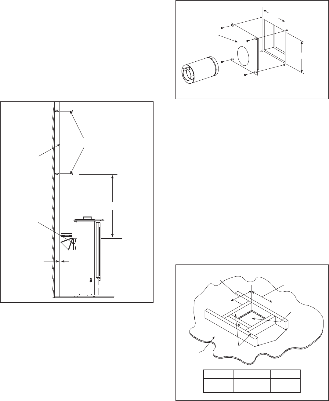
10 in. (254 mm)
10 in. (254 mm)
INTERIOR
WALL SHIELD
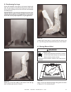
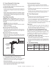
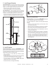
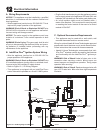
G. Install Firestops
For Horizontal Runs - Firestops are REQUIRED on both
sides of a combustible wall through which the ue passes.
To install restops (heat shield) for horizontal runs that pass
through either interior or exterior walls:
• Cut a 10 inch by 10 inch (254 mm X 254 mm) hole
through the wall.
• Position the restops on both sides of the hole previously
cut and secure the restops with nails or screws.
• The pipe opening of the restops MUST BE placed
towards the bottom of the restop.
• Continue the ue run through the restop.
Figure 10.13 Flue Pipe & Firestop
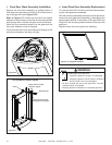
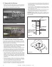
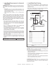
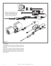
CEILING
NEW
FRAMING
MEMBERS
EXISTING CEILING
JOISTS
CHIMNEY
HOLE
A
B
Figure 10.14 Hole and New Framing Members
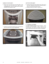
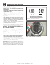
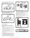
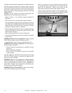
Figure 10.12 Installing Support Brackets
F. Install Support Brackets
For Horizontal Runs - The ue system must be supported
every 5 ft. (1.52 m) of horizontal run by a horizontal pipe
support. To install support brackets for horizontal runs:
• Place the pipe supports around the ue pipe.
• Nail the pipe supports to the framing members.
For Vertical Runs - The ue system must be supported
every 8 ft. (2.44 m) above the replace ue outlet by wall
brackets. To install support brackets for vertical runs:
• Attach wall brackets to the ue pipe and secure the wall
bracket to the framing members with nails or screws.
For Vertical Runs - One restop is REQUIRED at the hole
in each ceiling through which the ue passes.
To install restops for vertical runs that pass through
ceilings:
• Position a plumb bob directly over the center of the
vertical ue component.
• Mark the ceiling to establish the centerpoint of the ue.
• Drill a hole or drive a nail through this center point.
• Check the oor above for any obstructions, such as
wiring or plumbing runs.
• Reposition the replace and ue system, if necessary,
to accommodate the ceiling joists and/or obstructions.
• Cut a 9 in. x 9 in. (229 mm x 229 mm) hole when using
SLP pipe. Use the restop pipe opening as a guide.
• Frame the hole with framing lumber the same size as
the ceiling joists.
A B
SLP
9 in.
(229 mm)
9 in.
(229 mm)
WALL BRACKET
WALL STUD
2.44 m
FLUE
OUTLET
25.4 mm