


47
Heat & Glo • VRT-AUB • 2123-980 Rev. H • 5/12
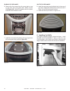
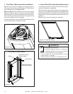
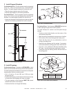
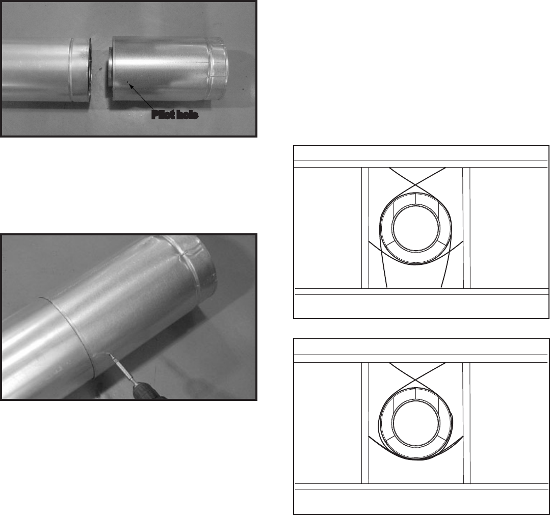
C. Secure The Vent Sections
• Vertical runs of pipe must be supported every 8 ft. (2.44 m).
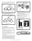
• Horizontal sections must be supported every 5 ft. (1.52
m).
• Vent supports or plumbers strap (spaced 120º apart)
may be used to support. See gures 10.5 and 10.6.
• Wall shield restops may be used to provide horizontal
support.
• Ceiling restops have tabs that may be used to provide
vertical support.
WARNING! Risk of Fire, Explosion or Asphyxiation!
Improper support may allow vent to sag and separate.
Use vent run supports and connect vent sections per in-
stallation instructions. DO NOT allow vent to sag below
connection point to appliance.
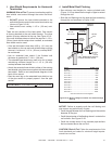
Figure 10.5 Securing Vertical Pipe Sections
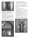
Figure 10.6 Securing Horizontal Pipe Sections
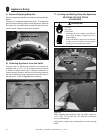
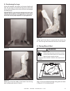
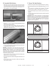
B. Assemble Slip Sections
• Slide the inner ue of the slip section into the inner ue
of the pipe section and the outer ue of the slip section
over the outer ue of the pipe section. See Figure 10.3.
• Slide together to the desired length.
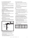
Figure 10.3 Slip Section Pilot Holes
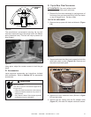
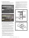
Figure 10.4 Screws into Slip Section
Pilot hole
• Continue adding pipe as necessary following instructions
in “Assembling Pipe Sections.”
NOTICE: If slip section is too long, the inner and outer
ues of the slip section can be cut to the desired length.
NOTICE: When installing a vent system with an HRC
termination cap, all pipe system joints shall be sealed
using a high temperature silicone sealant (149 ºC minimum
continuous exposure rating).
• Apply a bead of silicone sealant inside the female outer
pipe joint prior to joining sections.
• Only outer pipes are sealed, sealing the inner ue is not
required.
• All unit collar, pipe, slip section, elbow and cap outer
ues shall be sealed.
• Maintain a 1-1/2 in. (38 mm) overlap between the slip
section and the pipe section.
• Secure the pipe and slip section with two screws no
longer than 1/2 in. (13 mm), using the pilot holes in the
slip section. See Figure 10.4.