


23
Heat & Glo • VRT-AUB • 2123-980 Rev. H • 5/12
A. Flue Components
These models are approved to use Hearth & Home
Technologies series pipes, components and termination.
Approved components are labeled for identication. This
pipe is tested and listed as an approved component of
the stove.
DO NOT USE FIELD-FABRICATED FLUE COMPO-
NENTS. Refer to the flue manufacturer’s instructions.
This product is approved to be flued either horizontally,
through the side wall or vertically through the roof. You may
flue through a Class A or masonry chimney if an approved
adapter is used.
This gas stove is a balanced ue gas stove. All combus-
tion air must come directly from the outside of the building.
The ue pipe for this unit consists of an inner and an outer
pipe. The inner pipe carries the gas stove exhaust out of
the system, and the outer pipe brings fresh combustion air
into the gas stove.
• A round support box/wall thimble or heat shield is
required when the ueing passes through a combustible
wall.
• A support box or ceiling restop is required when the
ueing passes through a combustible ceiling.
• Roof ashing and a storm collar are required when ueing
passes through the roof.
• Follow instructions provided with the ueing for installation
of these items.
7
Flue Information
Fire Hazard.
Explosion Risk.
Asphyxiation Risk.
Do NOT connect this gas stove to a chimney
ue serving a separate solid-fuel or gas burning
gas stove.
• Flue this gas stove directly outside.
• Use separate ue system for this gas stove.
May impair safe operation of this gas stove or
other gas stoves connected to the ue.
CAUTION
ALL ue conguration specications MUST be followed.
• This product is tested and listed to these specications.
• Appliance performance will suffer if specications are not
followed.
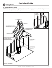
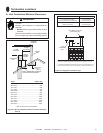
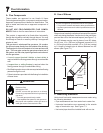
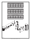
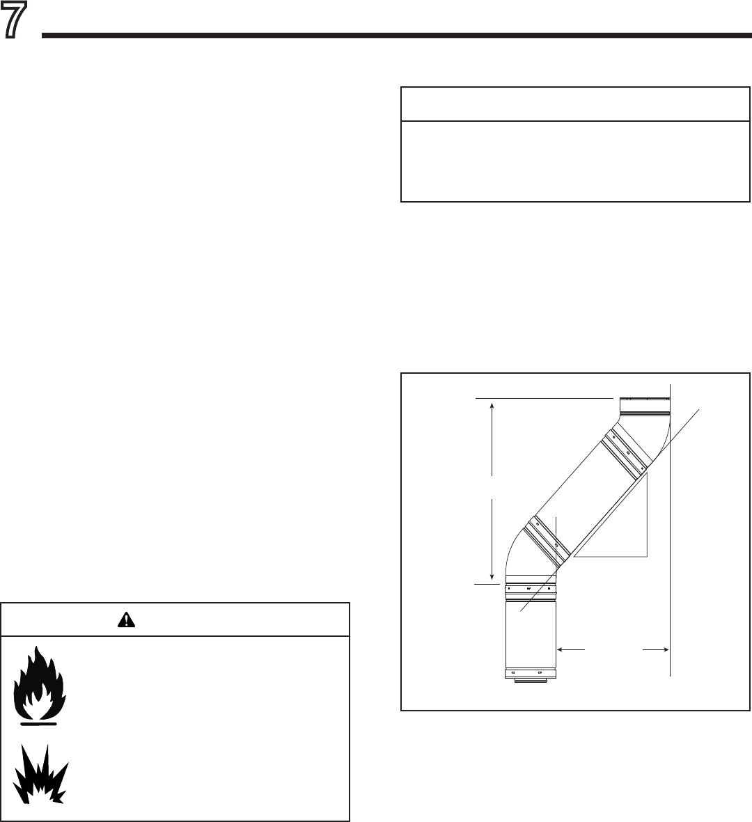
B. Use of Elbows
Figure 7.1
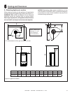
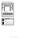
C. Measuring Standards
Vertical and horizontal measurements were made using
the following standards.
• Pipe measurements are from center line to center line.
• Horizontal terminations are measured to the outside
edge of termination cap. See Figure 7.3.
• Horizontal pipe should be installed level with no rise.
WARNING
Diagonal runs have both vertical and horizontal ue aspects
when calculating the effects. Use the rise for the vertical as-
pect and the run for the horizontal aspect (see Figure 7.1).
Two 45º elbows may be used in place of one 90º elbow.
On 45º runs, 12 in. (305 mm) of diagonal is equal to 8-1/2
in. (216 mm) horizontal run and 8-1/2 in. (216 mm) vertical
run. A length of straight pipe is allowed between two 45º
elbows (see Figure 7.1).
Horizontal
Vertical
8-1/2 in.
(216 mm)
8-1/2 in. (216 mm)
12 in.
(305 mm)