


Heat & Glo • ST-36TRB-IPI, PIER-36TRB-IPI, LCOR-36TRB-IPI, RCOR-36TRB-IPI • 2128-900 Rev. H • 8/1136
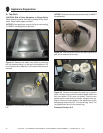
A. Pipe Clearances to Combustibles
WARNING! Risk of Fire! Maintain air space clearance to
vent. DO NOT pack insulation or other combustibles:
• Between ceiling fi restops
• Between wall shield fi restops
• Around vent system
Failure to keep insulation or other material away from
vent pipe may cause over heating and fi re.
8
8
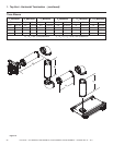
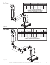
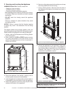
Vent Clearances and Framing
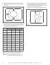
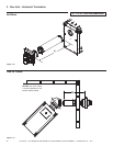
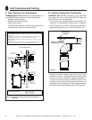
Figure 8.1 Horizontal Venting Clearances To Combustible
Materials
* When using SLP pipe, minimum clearances from the vent pipe to combustible materi-
als at wall shield firestops are: Top: 2-1/2 in. (64 mm)
Bottom: 1/2 in. (13 mm)
Sides: 1 in. (25 mm)
Note: Heat shields MUST overlap by a minimum of 1-1/2 in. (38 mm).
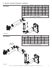
DVP heat shield - designed to be used on a wall 4 in. to 7-1/4 in. (102 mm to 184
mm) thick.
,f wall thickness is less than 4 in. the e[isting heat shields must be field trimmed. ,f
wall thickness is greater than 7-1/4 in. a DVP-HSM-B will be required.
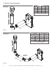
SLP heat shield - designed to be used on a wall 4-3/8 in. to 7-5/8 in. (111 mm to
194 mm thick).
,f wall thickness is less than 4-3/8 the e[isting heat shields must be field trimmed.
,f wall thickness is greater than 7-5/8 in. a DVP-HSM-B will be required.
(DVP-SLP Pipe Shown)
3 in. (76 mm)
top clearance *
1 in. (25 mm)
clearance
bottom & sides
Heat
Shield
Wall
Shield
Firestop
Heat
Shield
WALL
3 in. (76 mm)
top clearance *
1 in. (25 mm)
clearance
bottom & sides
Heat
Shield
Wall
Shield
Firestop
Heat
Shield
WALL
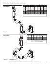
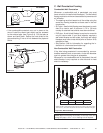
3 in. (76 mm)
top clearance
1 in. (25 mm)
clearance around
vertical sections
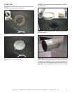
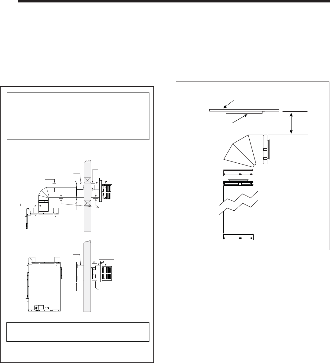
B. Continue Adding Vent Components
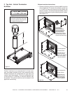
WARNING! Risk of Fire! Installation of this appliance
may require the use of heat shield 385-920 above the
fi rst 90
0
elbow in the venting system.
• The heat shield is required above the fi rst elbow if the
clearance to combustible surface above is between
three (3) and four (4) inches. A shield is not required for
clearances greater than four inches. See Figure 8.2.
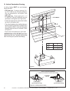
• Fasten the shield in place using the four pilot holes
provided in the part. The shield should be oriented such
that the 13-1/8 inch dimension (longest dimension) is
running in the same direction the elbow is pointing. The
shield should be centered directly above the elbow, and
positioned so that it creates a 1/2 inch airspace between
the shield and the combustible surface. See Figure 8.3.
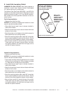
Figure 8.2
HEAT
SHIELD
3 in. MIN.
(76 mm)
COMBUSTIBLE
SURFACE
(Required for clearances
between 3 and 4 inches.)