


Heat & Glo • MTL-Insert • 2145-900 Rev. G • 6/0916
A. Wiring the Appliance
9
9
Electrical Information
Note: This appliance must be electrically wired and grounded
in accordance with local codes or, in the absence of local
codes, with National Electric Code ANSI/NFPA 70-latest
edition or the Canadian Electric Code, CSA C221.1.
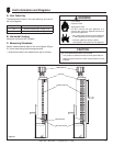
ON/OFF Switch
• An ON/OFF switch is included with the door/front and
should be attached to the door/front. The location of the
ON/OFF switch varies depending on model. It may be
installed on the valve cover plate or included with the
decorative surround. (See Installation instructions for
remote control).
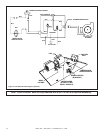
• If desired an additional wall switch or thermostat may
be added to system as shown in Figure 9.1. Follow
directions included with the optional wall switch.
Appliance Requirements
• This appliance DOES NOT require 110-120 VAC to
operate.
• It is recommended that a 110 VAC junction box be
connected for use with fan or remote control. (See Figure
9.2 for junction box wiring).
• Prevent accidental appliance operation when not attended.
• Unplug or remove batteries from remote control if absent or
if appliance will not be used for an extended period of time.
• Property damage possible from elevated temperatures.
CAUTION
ON
OFF
ON/OFF
SWITCH
REMOTE SWITCH
PIGTAIL
OPTIONAL WALL SWITCH,
THERMOSTAT OR REMOTE
STANDING
PILOT
WHT
RED
VALVE
Note: Electrical wiring must be installed by a licensed
electrician.
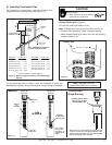
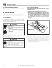
Figure 9.1 Standing Pilot Ignition Wiring Diagram
Wire 110V to electrical junction box.
Do NOT wire 110V to valve.
Do NOT wire 110V to wall switch.
• Incorrect wiring will damage millivolt valves.
• Incorrect wiring will override IPI safety lockout
and may cause explosion.
WARNING
• A 110-120 VAC circuit for this product must be protected
with ground-fault circuit-interrupter protection, in compliance
with the applicable electrical codes, when it is installed in
locations such as in bathrooms or near sinks.