


Heat & Glo • Grand-I35, Grand-I35-SP, Supreme-I30, Supreme-I30-SP • 2206-900 Rev. K • 6/11 40
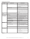
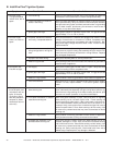
B. IntelliFire Plus™ Ignition System
Symptom Possible Cause Corrective Action
1. Pilot won’t light.
The ignitor/module
makes noise, but no
spark.
A. Incorrect wiring. Verify “S” wire (white) for sensor and “I” wire (orange) for ignitor are
connected to correct terminals on module and pilot assembly.
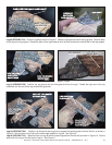
B. Loose connections or electrical
shorts in the wiring.
Verify no loose connections or electrical shorts in wiring from mod-
ule to pilot assembly. Verify connections underneath pilot assembly
are tight; also verify igniter and fl ame sense wires are not grounding
out to metal chassis, pilot burner, pilot enclosure, mesh screen if
present, or any other metal object.
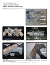
C. Ignitor gap is too large. Verify gap of igniter to right side of pilot hood. The gap should be
approximately .17 in. or 1/8 in. (3 mm).
2. Pilot won’t light,
there is no noise or
spark.
A. No power, transformer installed
incorrectly, or depleted batteries.
Verify that transformer is installed and plugged into module. Check
voltage of transformer at connection to module. Acceptable read-
ings of a good transformer are between 6.4 and 6.6 volts AC. Bat-
tery power supply voltage must be at least 4 volts. If below 4 volts,
replace batteries.
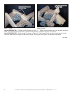
B. A shorted or loose connection in
wiring confi guration or wiring har-
ness.
Remove and reinstall the wiring harness that plugs into module.
Verify there is a tight fi t. Verify pilot assembly wiring to module. Re-
move and verify continuity of each wire in wiring harness. Replace
any damaged components.
C. Improper wall switch wiring. Verify that 120/VAC power is “ON” to junction box.
D. Module not grounded. Verify black ground wire from module wire harness is grounded to
metal chassis of appliance.
3. Pilot sparks, but
Pilot will not light.
A. Gas supply. Verify that incoming gas line ball valve is “open”. Verify that inlet
pressure reading is within acceptable limits.
B. Ignitor gap is too large. Verify gap of igniter to right side of pilot hood. The gap should be
approximately .17 in. or 1/8 in. (3 mm).
C. Module is not grounded. Verify module is securely grounded to metal chassis of appliance.
D. Pilot valve solenoid Verify that 1.5 to 1.8 VDC is supplied to pilot solenoid from module.
If below 1.5 volts, replace module. If 1.5 volts or greater, replace
valve.
4. Pilot lights but con-
tinues to spark, and
main burner will not
ignite. (If the pilot
continues to spark
after the pilot fl ame
has been lit, fl ame
rectifi cation has not
occurred.)
A. A shorted or loose connection in
fl ame sensing rod.
Verify all connections to wiring diagram in manual. Verify connec-
tions underneath pilot assembly are tight. Verify fl ame sense or ig-
niter wires are not grounding out to metal chassis, pilot burner, pilot
enclosure or screen if present, or any other metal object.
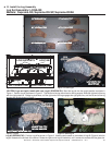
B. Poor fl ame rectifi cation or contami-
nated fl ame sensing rod.
With fi xed glass assembly in place, verify that fl ame is engulfi ng
fl ame sensing rod on left side of pilot hood. Flame sensing rod
should glow shortly after ignition. With a multi-meter, verify that cur-
rent in series between module and sense lead is at least 0.14 mi-
croamps. Verify correct pilot orifi ce is installed and gas inlet is set to
pressure specifi cations. Clean fl ame sensing rod with emery cloth
to remove any contaminants that may have accumulated on fl ame
sensing rod.
C. Module is not grounded. Verify module is securely grounded to metal chassis of appliance.
Verify that wire harness is fi rmly connected to the module.
D. Damaged pilot assembly or con-
taminated fl ame sensing rod.
Verify that ceramic insulator around the fl ame sensing rod is not
cracked, damaged, or loose. Verify connection from fl ame sensing
rod to white sensor wire. Clean fl ame sensing rod with emery cloth
to remove any contaminants that may have accumulated on fl ame
sensing rod. Verify continuity with a multi-meter with ohms set at
lowest range. Replace pilot if any damage is detected.