


Heat & Glo • CF230E-B & CF260E-B • 4038-894 Rev C • 11/05
9
4
4
Installation
Sharp Edges
• Wear protective gloves and safety
glasses during installation.
CAUTION
Shock Risk
Improperly grounded outlets could cause
electrical shock.
• Always use properly grounded, fused and
polarized outlets.
• Always use ground fault protection where
required by electrical code.
WARNING
Shock Risk
Fire Risk
Improperly protected power cords could
cause electrical shock or fi re.
• Do not pinch the cord or lay against a
sharp object.
• Do not cover the cord with carpeting, throw
rugs or runners.
• Secure and arrange cord to avoid a
tripping hazard.
• Do not coil cord.
WARNING
A. As a Fireplace
Select a suitable location that is not susceptible to moisture
and is away from drapes, furniture and high traffi c areas.
Wall Cabinet Kit, Corner Cabinet Kit or Custom
Cabinet Installation
The Cabinet must provide access to the wall outlet.
• For ease of electrical hookup, you may wish to install the
heater near an existing outlet. A 15 amp, 120 volt circuit is
required. A dedicated circuit is preferred but not essential
in all cases. A dedicated circuit will be required if, after
installation, the circuit trips or fuse blows on a regular basis
while the heater is operating. Additional heaters on the
same circuit may exceed the current rating of the circuit
breaker.
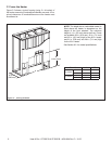
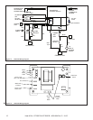
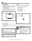
• If using a wall cabinet or corner cabinet, refer to the
installation instructions supplied with the kit. For custom
cabinets, frame and construct with the opening and depth
dimensions listed in Figures 3.1 and 3.2.
• Before plugging the heater into the wall outlet, make sure
all control switches are in the “OFF” position.
• Before fi nishing the cabinet, the heater must be set into the
cabinet and the power cord routed to the electrical outlet.
If the power cord does not reach the outlet, a No. 16-AWG
minimum wire size extension cord rated for a minimum of
1875 watts may be used. Use minimum length and do not
coil cord.
• To complete the heater installation, refer to Section 5.
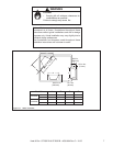
Non-Cabinet or Chase Installation
• Follow recommended framing dimensions in Figures 3.1
and 3.2.
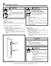
• Set the heater into the framed opening. Secure the heater
in place using the nailing fl anges on both sides of the
heater and nail to the framing.
• To fi nish out the heater, follow the instructions found in
Section 6.
• To complete heater installation, see Section 5.
Note: Follow all national and local electrical
codes.