


Heat & Glo • Cerona-36, Cerona-42 • 2106-900 Rev. F • 04/08 33
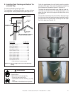
WHITE
JUNCTION
BOX
STRAIN RELIEF
CONNECTOR
FRONT OF
FIREPLACE
COPPER GROUND
ATTACHED TO
GROUND
SCREW WITH
GROUND WIRE
HEAT SHIELD
BOTTOM PAN
GROUND WIRE
INSIDE BOX
BLACK
14/2WG
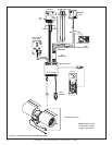
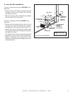
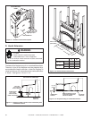
D. Junction Box Installation
Figure 10.2 Junction Box Detail
Note: Do NOT wire
110VAC to wall switch.
If the box is being wired from the OUTSIDE of the
appliance:
• Loosen screw on the Romex connector, feed the
necessary length of wire through the connector
and tighten the screw.
• Make all necessary wire connections and reattach
the cover plate to the outer shell.
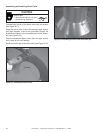
If the box is being wired from the INSIDE of the
appliance:
• Remove the screw attaching the junction box to
the outer shell, rotate the junction box inward to
disengage it from the outer shell (see Figure 10.2).
• Loosen the screw on the Romex connector, feed
the necessary length of wire through the connector
and tighten the screw.
• Pull the electrical wires from outside the appliance
through this opening into the valve compartment.
• Make all necessary wire connections to the
receptacle and assemble the receptacle and cover
to the junction box.