


Heat & Glo • BE-41C / LP, BE-41IPIC / LP • 2105-900 Rev. P • 6/0956
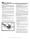
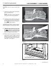
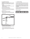
Figure 14.2 Fixed Glass Assembly
G. Fixed Glass Assembly
WARNING! Risk of Asphyxiation! Handle fi xed glass
assembly with care. Inspect the gasket to ensure it is
undamaged and inspect the glass for cracks, chips or
scratches.
• DO NOT strike, slam or scratch glass.
• DO NOT operate fi replace with glass removed, cracked,
broken or scratched.
• Replace as a complete assembly.
Removing Fixed Glass Assembly
• Pull the four glass assembly latches out of the groove on
the glass frame. Remove glass door from the appliance
(see Figure 14.2).
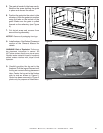
Replacing Fixed Glass Assembly
• Replace the glass door on the appliance. Pull out and
latch the four glass assembly latches into the groove on
the glass frame.
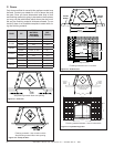
Air Shutter Settings
NG LP
Burner 3/8 in. Full Open
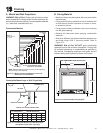
H. Install Trim and/or Surround
• Install optional trim kits and/or surrounds using the
instructions included with the accessory.
• Use non-combustible materials to cover the gap between
the sheet rock and the appliance (when applicable to the
model).
GLASS
ASSEMBLY
LATCHES
(BOTH BOTTOM
AND TOP)
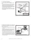
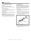
I. Air Shutter Setting
This appliance has an adjustable air shutter (which controls
the primary air) factory set for the minimum vertical vent
run. If your installation has more than the minimum required
vertical vent length, adjustment of the air shutter may
be necessary to obtain optimal fl ame appearance. This
should be adjusted by a qualifi ed installer at the time
of installation.
To adjust the air shutter, remove the burner and rotate
the shutter on the end of the burner neck. Care should be
taken when adjusting the air shutter so as not to cause
the appliance to soot. If sooting occurs the air shutter will
need to be rotated open.