


5
Vent System Installation Precautions
Before starting installation of vent kits, the installer
should read these instructions and the Vent Kit
Instructions to ensure that a proper vent installation is
completed.
Consult your local Building Codes before beginning
the Installation.
WARNING
THIS GAS INSERT AND VENT
ASSEMBLY MUST BE VENTED
DIRECTLY TO THE OUTSIDE AND
MUST NEVER BE ATTACHED TO A
CHIMNEY SERVING A SEPARATE
SOLID FUEL BURNING APPLIANCE.
EACH GAS APPLIANCE MUST USE A
SEPARATE VENT SYSTEM. COMMON
VENT SYSTEMS ARE PROHIBITED.
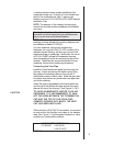
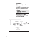
Vent System Approvals
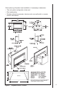
Table 1 and Figure 3 through 5 shows the vent
termination caps and systems approved for the use
with these models. Approved vent system
terminations are labeled for identification. 3-inch
diameter listed flexible aluminum or stainless steel
gas vent is used for both the incoming combustion air
and exhaust vent pipes. NO OTHER VENTING
SYSTEMS OR COMPONENTS MAY BE USED.
Detailed installation instructions are included with
each vent termination kit and should be used in
conjunction with this manual.
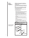
Horizontal Venting
The vent system on this model CANNOT be
terminated horizontally.
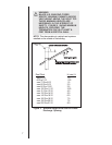
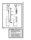
Vertical Venting
The vent pipes MUST be connected to the proper
collars on the unit AND the exhaust vent pipe MUST
be connected to the termination cap or the unit will not
operate. The combustion air vent pipe CAN be
connected to the termination cap or it can terminate
inside the chimney. The bottom opening of the
chimney must be sealed around the vent pipes if the
combustion air vent is NOT connected to the
termination cap. See Figures 3, 4 and 5.
NOTE: The minimum vertical rise (exhaust vent) is
14 feet and the maximum vertical rise is 50 feet.
These dimensions are measured from the starting
collars of the unit to the end of the last section of vent
pipe See dimension V in Figure 3.
3
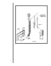
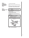
Installing the
Insert
Step 1
Installing the
Vent System