


Heat & Glo • 6000TV-OAK, 6000TV-OAK-IPI • 384-900 Rev. N • 11/05
17
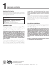
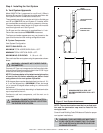
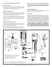
For Intermittent Pilot Ignition (IPI) Wiring
3 Volt Transformer
This appliance comes with a 3 volt transformer. The trans-
former plugs into the junction box and the two leads plug
into the green control module (see Figure 12).
Appliance Requirements
This appliance requires that 110-120 VAC be wired to the
junction box included in the manual bag assembly. Maintain
correct polarity when wiring the junction box.
The junction box is installed by sliding one tab of the box
through the slot on the lower right side of the outer wrap
and driving a screw through the other tab into the pilot hole
on the outer wrap.
Operation using Battery Power
This fireplace has an optional battery operation. The sys-
tem is fully functional with the use of two “D” size batteries
without ordinary 110-120 VAC power.
Wiring to the battery pack should be left disconnected in
order to conserve battery life. In the case of a loss of power,
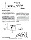
Figure 12. Intermittent Ignition (IPI) Wiring Diagram
simply connect red and black wire leads to activate battery
power (connect red to red, black to black). The fireplace
can be used as necessary. Once power (110 VAC) is re-
stored, disconnect red and black wire leads to extend bat-
tery life.
Optional Accessories
Optional fan and remote control kits require that 110-120
VAC be wired to the fireplace junction box.
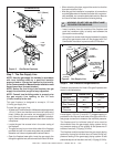
Wall Switch
Position the wall switch in the desired position on the wall. An
assembly of 18 ft of 20 AWG is provided with the fireplace to
connect the wall switch to the appliance. Instead of the supplied
assembly, wire with a length of 25 ft or less and a gauge of 20
AWG through 14 AWG is acceptable. The wire needs a jacket
with a temperature rating of 140
o
F (60
o
C) or higher. At the
appliance connect the wire to the ON/OFF switch pigtails.
CAUTION: LABEL ALL WIRES PRIOR TO DISCONNEC-
TION WHEN SERVICING CONTROLS. WIRING ERRORS
CAN CAUSE IMPROPER AND DANGEROUS OPERA-
TION. VERIFY PROPER OPERATION AFTER SERVICING.
NOTE 1: Ignition module, valve, pilot and
wall switch operate on 3 volts. 120 VAC
is required at junction box unless
equipped with battery back-up.
NEUTRAL
GROUND
REMOTE
CONTROL
HOT
LOW VOLTAGE
SEE NOTE 1
ON/OFF
WALL SWITCH
VALVE
TRANSFORMER OUTLET
PLUG-IN
3V TRANSFORMER
FLAME SPARKER /
SENSOR
LOW VOLTAGE
SEE NOTE 1
OPTIONAL
BATTERY
BACK-UP
IGNITION
MODULE
(3V)
ORANGE
(IGNITOR)
WHITE
(SENSOR)
S
I
IGNITION MODULE 3 VAC
INTERMITTENT PILOT IGNITOR
GROUND TO
FIREPLACE
CHASSIS
GREEN
ORANGE
VALVE
TEMP SENSOR
OPTIONAL BATTERY PACK
TRANSFORMER
3 VAC
PLUG-IN
FAN
REM/AUX
TRANS
NEUTRAL
HOT
5 4 3 2 1
5 4 3 2 1
BLACK
RED
BROWN
B
R
O
W
N
Î