


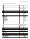
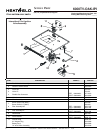
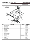

Heat & Glo • 6000TV-OAK, 6000TV-OAK-IPI • 384-900 Rev. N • 11/0516
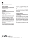
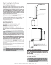
Step 9. Wiring the Fireplace
NOTE: Electrical wiring must be installed by a licensed
electrician.
CAUTION: DISCONNECT REMOTE CONTROLS IF AB-
SENT FOR EXTENDED TIME PERIODS TO PREVENT
ACCIDENTAL FIREPLACE OPERATION.
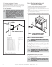
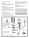
For Standing Pilot Ignition Wiring
Appliance Requirements
• This appliance DOES NOT require 110-120 VAC to operate.
WARNING: DO NOT CONNECT 110-120 VAC
TO THE GAS CONTROL VALVE OR THE AP-
PLIANCE WILL MALFUNCTION AND THE
VALVE WILL BE DESTROYED.
Optional Accessories
Optional fan and remote control kits require that 110-120
VAC be wired to the factory installed junction box before
the fireplace is permanently installed.
!
!
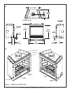
Figure 10. Standing Pilot Ignition Wiring Diagram
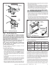
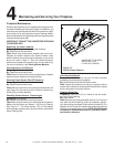
Figure 11. Fan Wiring Diagram
Wall Switch
Position the wall switch in the desired position on the wall. An
assembly of 18 ft of 20 AWG is provided with the fireplace to
connect the wall switch to the appliance. Instead of the sup-
plied assembly, wire with a length of 25 ft or less and a gauge
of 20 AWG through 14 AWG is acceptable. The wire needs a
jacket with a temperature rating of 140
o
F (60
o
C) or higher. At
the appliance connect the wire to the ON/OFF switch pigtails.
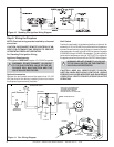
WARNING: DO NOT CONNECT 110-120 VAC
TO THE WALL SWITCH OR THE CONTROL
VALVE WILL BE DESTROYED.
CAUTION: LABEL ALL WIRES PRIOR TO DISCON-
NECTION WHEN SERVICING CONTROLS. WIRING
ERRORS CAN CAUSE IMPROPER AND DANGEROUS
OPERATION. VERIFY PROPER OPERATION AFTER
SERVICING.
NOTE: IF ANY OF THE ORIGINAL WIRE
AS SUPPLIED WITH THE APPLIANCE
MUST BE REPLACED, IT MUST BE
REPLACED WITH TYPE 105 C RATED WIRE.
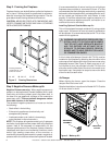
O
JUNCTION BOX
VARIABLE SPEED CONTROL
TEMPERATURE
SENSOR SWITCH
WHT
GRN
BLK
BLK
110-120 VA
C
BLOWER
BLOWER RECEPTACLE
BLK
BLK
BLK
BLK
WHT
GROUND
WHT
BLK
BLK
BLK
BLOWER
SENSOR
SWITCH
“FAN”
RECEPTACLE
SPEED
CONTROL