


Heat & Glo • 6000TRI-IPI, 6000TRI-SP • 385-901 Rev. F • 5/0530
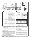
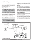
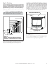
Figure 38. Fan Wiring Diagram
NOTE: IF ANY OF THE ORIGINAL WIRE
AS SUPPLIED WITH THE APPLIANCE
MUST BE REPLACED, IT MUST BE
REPLACED WITH TYPE 105 C RATED WIRE.
O
JUNCTION BOX
VARIABLE SPEED CONTROL
TEMPERATURE
SENSOR SWITCH
WHT
GRN
BLK
BLK
110-120 VAC
BLOWER
BLOWER RECEPTACLE
BLK
BLK
BLK
BLK
WHT
GROUND
WHT
BLK
BLK
BLK
BLOWER
SENSOR
SWITCH
“FAN”
RECEPTACLE
SPEED
CONTROL
NOTE: Electrical wiring must be installed by a licensed
electrician.
CAUTION: DISCONNECT REMOTE CONTROLS IF AB-
SENT FOR EXTENDED TIME PERIODS. THIS WILL PRE-
VENT ACCIDENTAL FIREPLACE OPERATION.
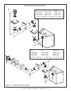
For Standing Pilot Ignition Wiring (see Figure 37).
Appliance Requirements
• This appliance DOES NOT require 110-120 VAC to operate.
WARNING: DO NOT CONNECT 110-120 VAC TO
THE GAS CONTROL VALVE OR WALL SWITCH
OR THE APPLIANCE WILL MALFUNCTION
AND THE VALVE WILL BE DESTROYED.
!
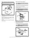
Step 9. Wiring the Fireplace
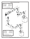
Intermittent Pilot Ignition (IPI) Wiring
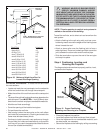
3 Volt Transformer
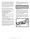
This appliance comes with a 3 volt transformer found in the
manual bag. Plug the transformer leads to the green con-
trol module (see Figure 36). Then plug the transformer into
the side outlet on the junction box.
!
Appliance Requirements
• This appliance DOES NOT require 110-120 VAC to operate.
WARNING: DO NOT CONNECT 110-120 VAC
TO THE GAS CONTROL VALVE OR THE AP-
PLIANCE WILL MALFUNCTION AND THE
VALVE WILL BE DESTROYED.
Operation using Battery Power
This fireplace has an optional battery operation. The sys-
tem is fully functional with the use of two “D” size batteries
without ordinary 110-120 VAC power.
Wiring to the battery pack should be left disconnected in
order to conserve battery life. In the case of a loss of power,
simply connect red and black wire leads to activate battery
power (connect red to red, black to black). The fireplace
can be used as necessary. Once power (110 VAC) is re-
stored, disconnect red and black wire leads to extend bat-
tery life.
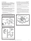
Optional Accessories
Optional fan and remote control kits require that 110-120
VAC be wired to the factory installed junction box before
the fireplace is permanently installed (see Figure 38)
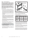
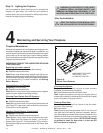
Wall Switch
Position the wall switch in the desired position on a wall.
Run a maximum of 25 feet (7.8 m) or less length of 18
A.W.G. minimum wire and connect it to the fireplace ON/
OFF switch pigtails.
CAUTION: LABEL ALL WIRES PRIOR TO DISCONNEC-
TION WHEN SERVICING CONTROLS. WIRING ERRORS
CAN CAUSE IMPROPER AND DANGEROUS OPERATION.
VERIFY PROPER OPERATION AFTER SERVICING.