


Heat & Glo • 6000TRI-IPI, 6000TRI-SP • 385-901 Rev. F • 5/0516
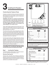
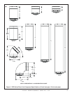
HORIZONTAL VENTING
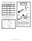
Kit No. H Max. Run
DVP-TRAP 24" (610 mm)
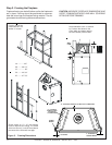
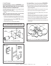
Figure 11. Corner Installation
NOTE: This model is tested and approved to use
45° elbows in corner installations. However, 90°
elbows will result in better performance. The
use of two 90
0
elbows in a corner installation
will affect space requirements (see Figure 2).
45-DEGREE
ELBOW
90-DEGREE
ELBOWS
H
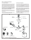
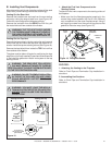
3. Match the amount of vertical you have in the sys-
tem with the chart to find the appropriate position
to set the Flue Restrictor (see Figure 9).
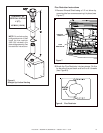
1 2 3 4 5
SETTINGS
1 2 3 4 5
Figure 10
- CHART -
Vertical
Top Vent
NG
Top Vent
LP
Rear Vent
NG
Rear Vent
LP
4' 1-1
No
Restrictor
No
Restrictor
No
Restrictor
8' 2-2 1-2 1-1
No
Restrictor
15' 3-3 3-2 2-2 1-2
20' 3-4 3-3 3-3 2-3
25' 3-4 3-3 3-3 2-3
30' 4-4 3-4 3-4 3-3
35' 4-4 3-4 3-4 3-3
40' 5-4 4-4 4-4 3-4
4. Center the Flue Restrictor on vent and secure in
place by using two self-tapping screws.
5. Reinstall the Exhaust Shield.
Figure 9