


Heat & Glo • 6000G, 6000G-IPI • 2103-900 Rev. M • 9/08 7
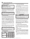
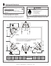
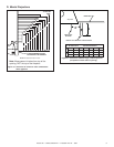
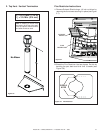
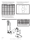
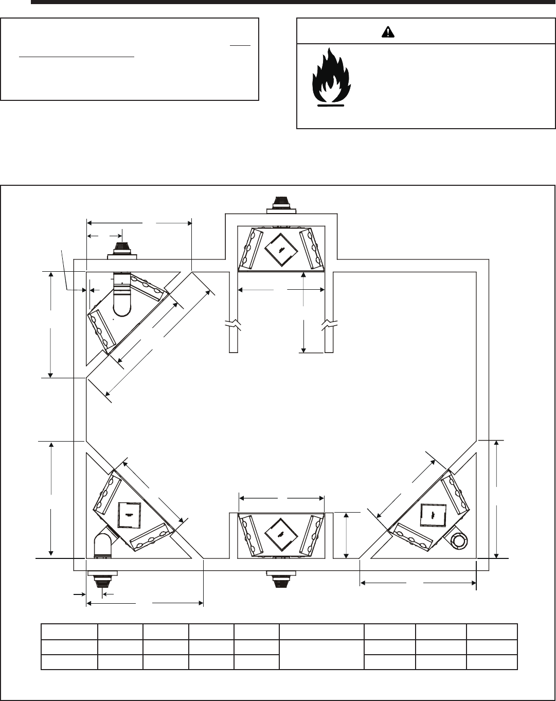
Figure 3.1 Appliance Locations
In addition to these framing dimensions, also reference the following sections:
• Clearances and Mantel Projections (Sections 3.C and 3.D)
• Vent Clearances and Framing (Section 6).
1/2 IN.
REAR VENT,
HORIZONTAL TERMINATION,
TWO ELBOWS
REAR VENT,
NO ELBOWS
REAR VENT,
ONE ELBOW
ALCOVE
INSTALLATION
TOP VENT
ONE 90º ELBOW
A
A
B
C
B
E
D
B
D
B
B
D
D
F
G
H
ABCD E F G H
Inches 51 42 72 56-5/8
See Section D.
Mantel Projections
22 17-3/4 8
Millimeters 1295 1067 1829 1438 559 451 203
3
3
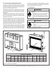
Framing and Clearances
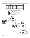
Note:
• Illustrations reflect typical installations and are FOR
DESIGN PURPOSES ONLY.
• Illustrations/diagrams are not drawn to scale.
• Actual installation may vary due to individual design
preference.
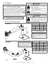
Fire Risk
Provide adequate clearance:
• Around air openings
• To combustibles
• For service access
Locate appliance away from traffi c areas.
A. Selecting Appliance Location
When selecting a location for your appliance it is important to
consider the required clearances to walls (see fi gure 3.1).
Note: For actual appliance dimensions refer to Sec-
tion 16.
WARNING