


8
Installation, Operation & Maintenance VMH 30/36 SERIES Heat Controller, Inc.
3
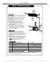
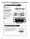
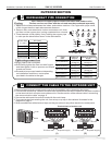
REFRIGERANT PIPE CONNECTION
1. ut a pipe with a pipe cutter,
a little longer than the required measured distance.
2. Remove flare nuts attached to indoor and outdoor unit, then
put them on the copper pipe, having completed burr removal.
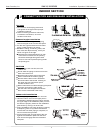
3. Flare the ends of the pipe by firmly holding the copper pipe
in a die per the dimensions shown in the table below.
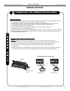
Measure the distance between the indoor and outdoor sections. C
Align pipes to be connected.
Sufficiently tighten the flare nut with fingers,
and then tighten it with a spanner and torque
wrench as shown.
Excessive torque can break nut d
epending
on installation conditions, use torques
provided in the table to the right.
Outer diam.
in. (mm)
A in.(mm)
Max.
Min.
Ø3/4”(Ф
19)
.
Outer
diam.
Tightening
torque
Additional tightening
torque
Ø1/4”(Ф
6.35mm)
11.07
(153kgf.cm)
.
ft lbf
.
11.79 ft lbf
(163kgf.cm)
25.82
(357kgf.cm)
.
ft lbf
33.20
(459kgf.cm)
.
ft lbf
47.95
(663kgf.cm)
.
ft lbf
26.55
(367kgf.cm)
.
ft lbf
36.65
(479kgf.cm)
.
ft lbf
49.40
(683kgf.cm)
.
ft lbf
18.44
(255kgf.cm)
.
ft lbf
19.17
(265kgf.cm)
.
ft lbf
Flaring
Tightening connection
U
N
I
T
Oblique
O
90
Roughness
Burr
Bar
Copper pipe
Clamp handle
Handle
Bar
"A"
Indoor unit tubing Flare nut Pipings
4
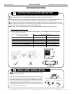
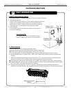
1. Remove the electrical control board cover from the outdoor unit by loosening the screw.
2. Connect the connective cables to the terminals as identified with their respective matched numbers
on the terminal block of indoor and outdoor units. See the section of the manual called “connecting
the communication cable” on page. 6.
3. Secure the cable onto the control board with the cord clamp.
4. To prevent water from entering the unit, form a loop or p-trap in the cable as ill
ustrated in the
diagram on page 3.
5. Wrap unused wires with electrical tape, so they do not touch any other electrical or metal parts.
CONNECT THE CABLE TO THE OUTDOOR UNIT
Terminal block of outdoor unit
Cover
Screw
To indoor unit
To indoor unit
To power supply
To power supply
L1 L2 S L1 L2
L1 L2 S L1 L2
(1)
(2)
Ø5/8”(Ф
16)
Ø1/2”(Ф
12.7)
Ø3/8”(Ф
9.52)
Ø1/4”(Ф
6.35)
.09”(2.4
)
.08”(2.2
)
.07”(1.8
)
.06”(1.6
)
.05”(1.3
)
.08”(2.0
)
.08”(2.0
)
.04”(1.0
)
.04”(1.0
)
.02”(0.7
)
Use a line set of copper pipe to connect the indoor and outdoor units.
The line set does not come with the unit and must be purchased separately.
Ø3/8”(Ф
9.52mm)
Ø1/2”(Ф
12.7mm)
Ø5/8”(Ф
16mm)
Ø3/4”(Ф
9mm)
.
.
OUTDOOR SECTION