


4
Installation, Operation & Maintenance VMH 30/36 SERIES Heat Controller, Inc.
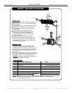
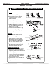
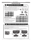
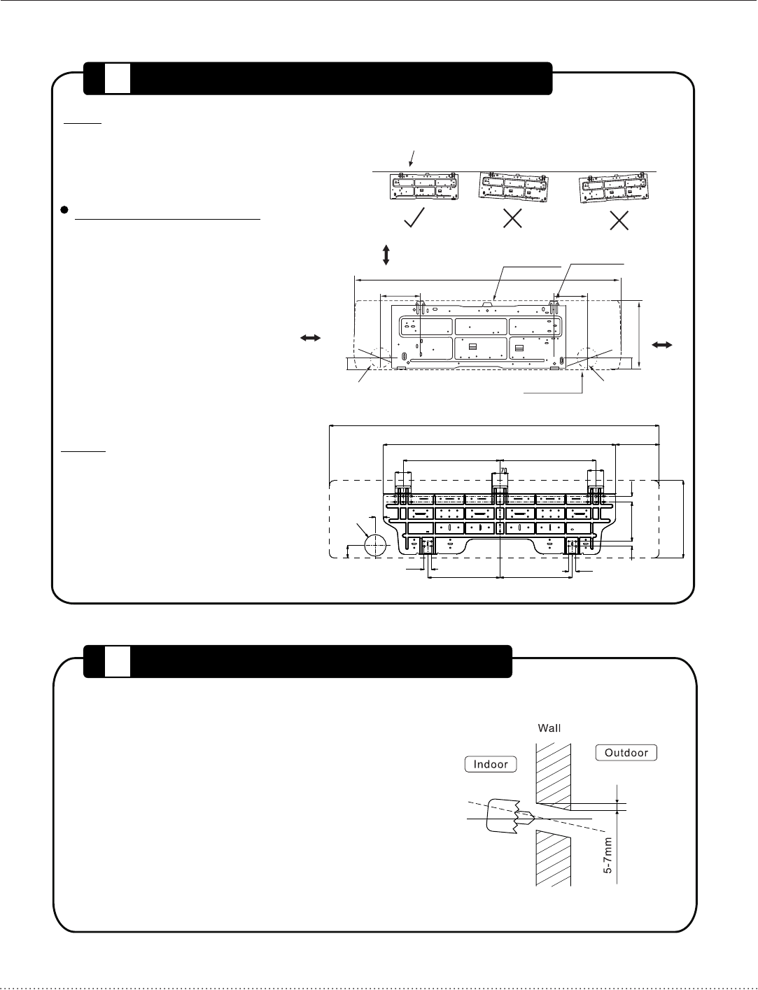
1. Fit the installation plate horizontally
on structural parts of the wall with
the appropriate clearance around the
installation plate.
2. Drill holes in the wall according to the
wall structure and corresponding
mounting points on the installation
plate. If the wall is made of brick,
concrete or the like, drill eight 3/16”(5mm)
diameter holes in the wall. Insert Clip
anchor for appropriate mounting screws.
3. Fit the installation plate on the wall
with eight (8) type “A” screws.
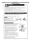
1. Determine hole positions according to left and right
side of the installation pla
te. The hole center is obtained
by measuring the distance as shown in the diagram above.
2. Drill the piping plate hole with Ø2.55in(65mm) hole-core drill.
3. Drill the piping hole at either the right or the left and the
hole should be slightly slanted to the outdoor side.
4. Always use wall hole conduit when drilling metal grid,
metal plate or the like.
DRILL A HOLE IN THE WALL
FIT THE INSTALLATION PLATE
2
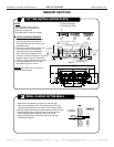
Fit the Installation Plate
1
The installation plate provided
with the machine may differ from
appliance to appliance.
(Use wall studs for best anchorage)
5 inches (120mm)
from the wall
1.8 (45)”
Pipe hole
6 inches (150mm) or more
from the ceiling
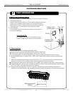
Model A
Model B
12.8 (325)
”
Ø2.6”(Ø65)
Ø ” Ø2.6 ( 65)
5.2 (133)”
Flange
Flange
Pipe
hole
Indoor unit outline
Correct orientation
of Installation Plate
1.25 (32)”
12.5 (318)”
12.5”(318)
1.25 (32)”
6.1 155)”
1.4 (35)”
3.7 (Ø95)”
2.8 (70)”
16.84 (426)” 16.6 (422)”
2.8 (71)”
3.36ft.(1023)
4.75ft.(1450)
7.5 (190)”
13.4 340)”(
0.98 (25)”
6.9”(174)
0.79 (20)”
4.75ft.(1250)
6”(150)
5 inches (120mm)
or more from
the wall
1.8 (45)
”
NOTE:
NOTE: Dimensions are in inches (mm)
unless otherwise stated.
INDOOR SECTION