


Page 6
R410a Application and Service Guide
An overcharged TXV unit can be identi ed by:
•
High subcooling
•
High head pressures
Even though R410a has a very small fractionation po-
tential it cannot be ignored completely when charging.
To avoid fractionation, charging a system with R410a
should be done with LIQUID from the tank to maintain
optimum system performance. To ensure the proper
blend of refrigerant is used, it is important that liquid
only be removed from the storage tank. Some cylinders
use dip tubes which allow liquid to be extracted from the
cylinder. These can be identi ed as recovery tanks with
yellow tops and gray bottom and have a dual liquid and
vapor valve assembly. Storage tanks without dip tubes
will need to be tipped upside down in order for liquid to
be removed. Once the liquid is removed from the storage
cylinder, it can be charged into the system in the vapor
state as long as all of the refrigerant is used from the
charging cylinder. Liquid charging can be accomplished
by using:
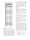
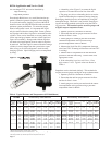
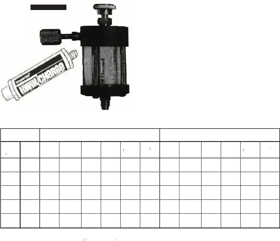
• A throttling valve (Figure 3) to ensure the liquid
vaporizes as it enters the suction line of the unit.
• Τhe gauge set valve as a throttling device to restrict
liquid from ooding the compressor during charging.
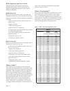
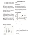
Recharging should always be accomplished by using the
nameplate charge. When this is not possible, charging us-
ing the subcooling method can be done using the follow-
ing procedure. This method requires accurate gauges and
a digital strap-on temperature meter.
1. Operate system for 10 minutes to stabilize.
2. Ensure that the unit has proper water and air ow
and the air lter is clean.
3. Attach gauges to discharge port and record the
saturation temperature at this pressure using a
pressure/temperature chart for R410a.
4. Measure the liquid line (LL) temperature (between
aircoil and TXV in heating and between coax and TXV
in cooling).
5. Subtract the LL temperature from the saturation
pressure to nd the subcooling. Consult Table 4 for
appropriate values.
6. If the subcooling is too low add 2-4 oz.; if too
high, remove 2-4 oz. Typical values are shown in
Table 4.
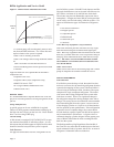
Superheat can be calculated similarly. This method also
requires accurate gauges and digital strap-on thermometer.
1. Operate system for 10 minutes to stabilize.
2. Ensure that the unit has proper water and air ow
and the air lter is clean.
3. Attach gauges to suction port and record the satura-
tion temperature at this pressure using a pressure/
temperature chart for R410a.
Figure 3. Throttling Valves
Figure 3. Throttling Valves
Table 4. Typical Pressure and Temperatures (HTV060 Shown)
HTV060
Full Load Cooling - without HWG active
Full Load Heating - without HWG active
Entering
Water
empºFT
emp F
T
W
ater
Flow GPM
Suction
Pressure
PSIG
Discharge
Pressure
PSIG
Super-heat
Sub-
cooling
Water
Temp RiseT
emp Rise
T
ºF
Air TempT
emp
T
DropºF DB
Suction
Pressure
PSIG
Discharge
Pressure
PSIG
Super-heat
Sub-
cooling
Water
Temp DropT
emp Drop
T
ºF
Air TempT
emp
T
RiseºF DB
7.5
1
17-127
170-190
27-32
15-20
18.2-20.2
17-23
66-76
282-302
10-16
9-14
8-10
19-25
30
1
1.3
1
16-126
143-163
28-33
13-18
12.6-14.6
17-23
69-79
285-305
10-16
9-14
6-8
19-25
15.0
1
15-125
135-155
29-34
12-17
7-9
17-23
72-82
289-309
10-16
10-15
4-6
20-26
7.5
128-138
238-258
16-21
14-19
20.5-22.5
21-27
90-100
310-330
1
1-17
12-17
1
1.3-13.3
24-30
50
1
1.3
126-136
222-242
21-26
13-18
14.9-16.9
21-27
95-105
313-333
1
1-17
12-17
8.5-10.5
25-31
15.0
125-135
205-225
26-31
12-17
9.2-1
1.2
21-27
99-109
316-336
1
1-17
12-17
5.7-7.7
26-32
7.5
135-145
315-335
10-15
14-19
21-23
22-28
1
15-125
337-357
12-18
14-19
14-16
28-35
70
1
1.3
134-144
296-316
12-17
13-18
15.5-17.5
22-28
120-130
341-361
12-18
14-19
10.6-12.6
29-36
15.0
133-143
276-296
15-20
1
1-16
10-12
22-28
126-136
345-365
12-18
15-20
7.3-9.3
30-37
7.5
139-149
408-428
10-15
15-20
20.1-22.1
21-27
157-167
390-410
15-20
14-19
18.2-20.2
37-45
90
1
1.3
138-148
386-406
10-15
13-18
14.8-16.8
21-27
161-171
394-414
15-20
14-19
13.9-15.9
38-46
15.0
138-148
364-384
10-15
1
1-16
9.5-1
1.5
21-27
166-176
398-418
15-20
15-20
9.6-1
1.6
39-47
7.5
144-154
515-535
8-13
14-19
19-21
20-26
11
0 1
1.3
143-153
493-513
8-13
13-18
14-16
20-26
15.0
142-152
469-489
8-13
12-17
9-1
1
20-26
HWG should be disabled for accurate chart comparison
*Based on Nominal 400 cfm per ton airflow and 70
°
F EA
T
F EATF EA
htg and 80/67
T htg and 80/67T
°
F EA
T
F EATF EA
cooling
T coolingT
**Cooling air and water numbers can vary greatly with changes in humidity
Subcooling is based upon the head pressure at compressor service port