


Connecting the Cable between Indoor Unit and Outdoor Unit
Installation Manual 19
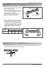
Connecting the Cable between Indoor Unit and Outdoor Unit
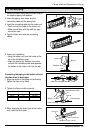
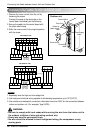
Connect the cable to the indoor unit by connecting the wires to the terminals on the control
board individually according to the outdoor unit connection. (Ensure that the color of the wires
of the outdoor unit and the terminal No. are the same as those of the indoor unit.)
The earth wire should be longer than the common wires.
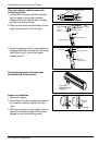
The circuit diagram is not subject to change without notice.
When installing, refer to the electrical diagram behind the front panel of Indoor Unit.
The wiring for the outdoor unit can be found on the inside of the Outdoor Unit control cover.
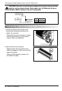
Connect the cable to the Indoor unit.
WARNING:
• The circuit diagram is not subject to change without notice.
• Be sure to connect wires according to the wiring diagram.
• Connect the wires firmly, so that not to be pulled out easily.
• Connect the wires according to color codes by referring to the wiring diagram.
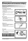
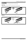
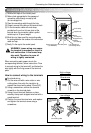
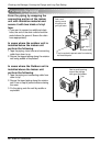
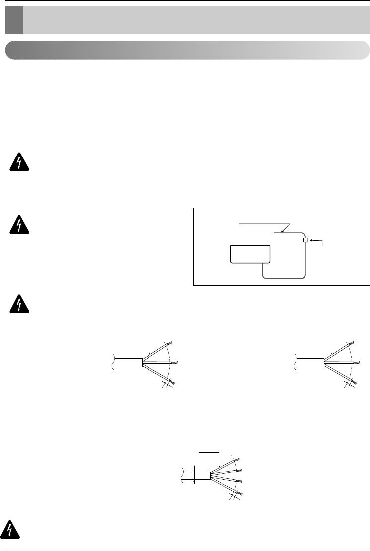
WARNING: Provide a circuit
breaker between power source
and the outdoor unit as shown
below.
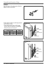
WARNING! :The power wire to the outdoor unit must be of sufficient gauge
to meet the Minimum Circuit Ampacity (MCA) as indicated on the outdoor
unit rating plate and be of type required by NEC and local codes.
The connecting cable between the indoor and outdoor unit should be SJOW
type, minimum 18 gauge, and meet requirements of NEC and local codes.
Air
Conditioner
Main power source
Circuit Breaker
Use a circuit breaker
or time delay fuse.
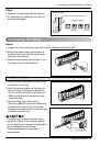
G
N
/Y
L
2
0
m
m
Line voltage (208~230V)
24k 36k
G
N
/Y
L
2
0
m
m
Line voltage (208~230V)
G
N
/Y
L
2
0
m
m
AWG18
Low voltage (below 40V)
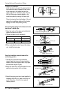
WARNING! Secure the interconnecting on both ends by using the clamps
provided.