


- 77 -
Service Manual
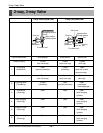
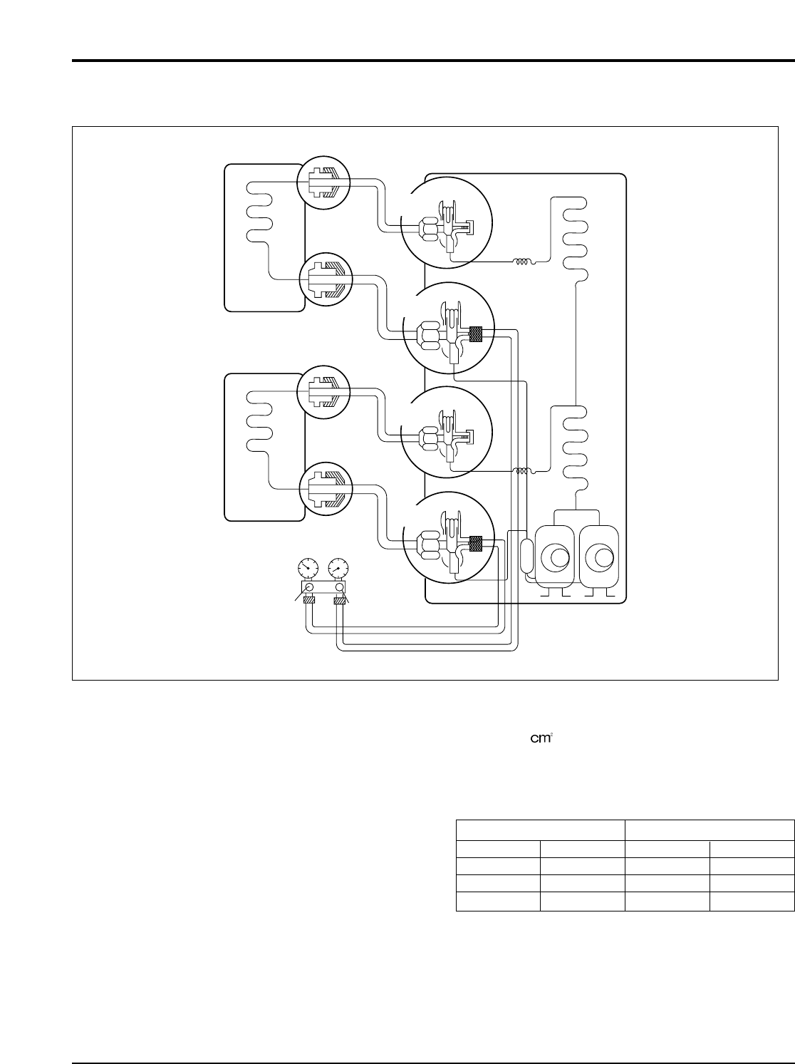
2-way, 3-way Valve
•
Be sure not to short the pressure switch S/W, otherwise if the low pressure switch S/W detects low pressure it will stop the compressor.
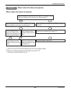
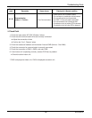
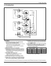
(1) Pumping down
• Procedure
1. Confirm that both the gas side and liquid side
valves are set to the open position.
- Remove the valve stem caps and confirm that the
valve stems are in the raised position.
- Be sure to use a hexagonal wrench to operate
the valve stems.
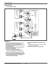
2. Operate the unit for 10 to 15 minutes.
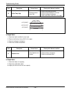
3.
Stop operation and wait for 3 minutes, then connect the
manifold gauge to the service port of the gas side valve.
- Connect the hose of the gauge with the push pin
to the service port.
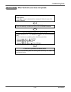
4. Air purging of the charge hose.
- Open the Low-handle valve on the gauge
slightly to air purge from the hose.
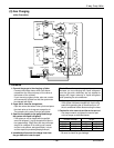
5. Set the liquid side valve to the closed position.
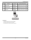
6.
Operate the air conditioner at the cooling cycle and
stop it when the gauge indicates 1kgf/cm
2
(14.22psi).
7.
Immediately set the gas side valve to the closed position.
- Do this quickly so that the gauge ends up indicat-
ing 1kg/
(14.22psi)
.
8.
Disconnect the charge set, and replace the liquid side
and gas side valve caps and the service port nut.
- Use torque wrench to tighten the service port nut to
a torque as indicated below.
- Be sure to check for gas leakage.
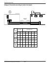
Indoor unit
Outdoor unit
Liquid side
Close
Gas side
2-Way
valve
Open
3-Way
valve
manifold gauge
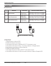
Indoor unit
Liquid side
Close
Gas side
2-Way
valve
Open
3-Way
valve
Hi- handle
(CLOSE)
Low-
handle
(CLOSE)
Outside diameter Turque
mm inch kg
.
m lbf
.
in
Ø6.35 1/4 1.8 156.2
Ø9.52 3/8 4.2 364.5
Ø12.7 1/2 5.5 477.4