


—8—
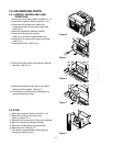
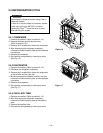
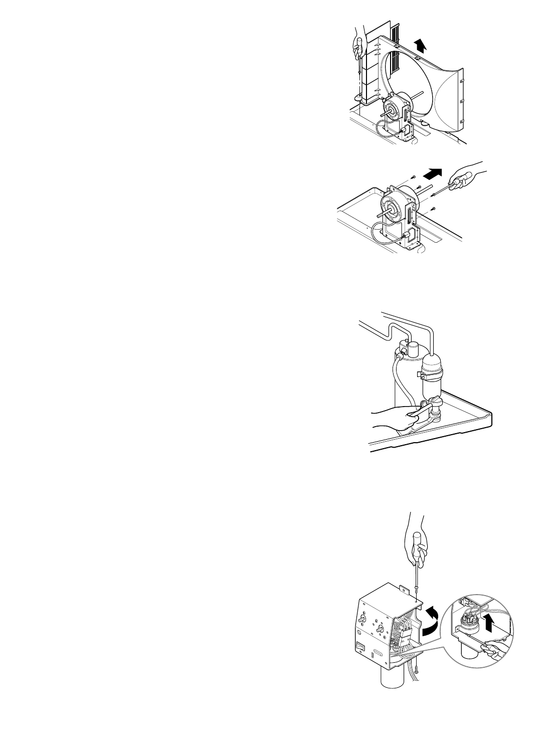
2.2.3 SHROUD
1. Remove the fan. (Refer to section 2.2.2)
2. Remove the screw which fasten the shroud.
3. Remove the shroud. (See Fig. 9)
4. Re-install the component by referring to the
removal procedure, above.
2.3 ELECTRICAL PARTS
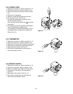
2.3.1 MOTOR
1. Remove the cabinet. (Refer to section 2.1.2)
2. Remove the clamp cord and disconnect a wire
housing in control box. (Refer to section 2.1.3)
3. Remove the turbo fan. (Refer to section 2.2.2)
4. Remove the fan. (Refer to section 2.2.2)
5. Remove the 4 or 2 screws which fasten the motor.
(See Fig. 10)
6. Remove the motor.
7. Re-install the components by referring to the
removal procedure, above.
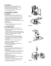
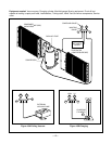
2.3.2 COMPRESSOR
1. Remove the cabinet. (Refer to section 2.1.2)
2. Discharge the refrigerant system using Freon
TM
Recovery System.
If there is no valve to attach the recovery system,
install one (such as a WATCO A-1) before venting
the Freon
TM
. Leave the valve in place after
servicing the system.
3. Disconnect the 3 leads from the compressor.
4. After purging the unit completely, unbraze the
suction and discharge tubes at the compressor
connections.
5. Remove the 3 nuts and the 3 washers which
fasten the compressor. (See Fig. 11)
6. Remove the compressor.
7. Re-instill the components by referring to the
removal procedure, above.
2.3.3 CAPACITOR
1. Remove the control box. (Refer to section 2.1.3)
2. Remove knobs and the tips which fasten the
display panel.
3. Disconnect the 2 leads from the rocker switch and
remove the panel (Energy saver model only).
4. Remove 2 screws and unfold the control box.
(See Fig. 12)
5. Remove the Rotary Switch.
6. Remove the screw and the clamp which fastens
the capacitor. (See Fig. 12)
7. Disconnect all the leads of capacitor terminals.
8. Re-install the components by referring to the
removal procedure, above.
Figure 9
Figure 10
Figure 11
Figure 12