


62
Heat & Glo • TRUE-36, TRUE-42, TRUE-50 • 2282-900 Rev. D • 8/12
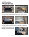
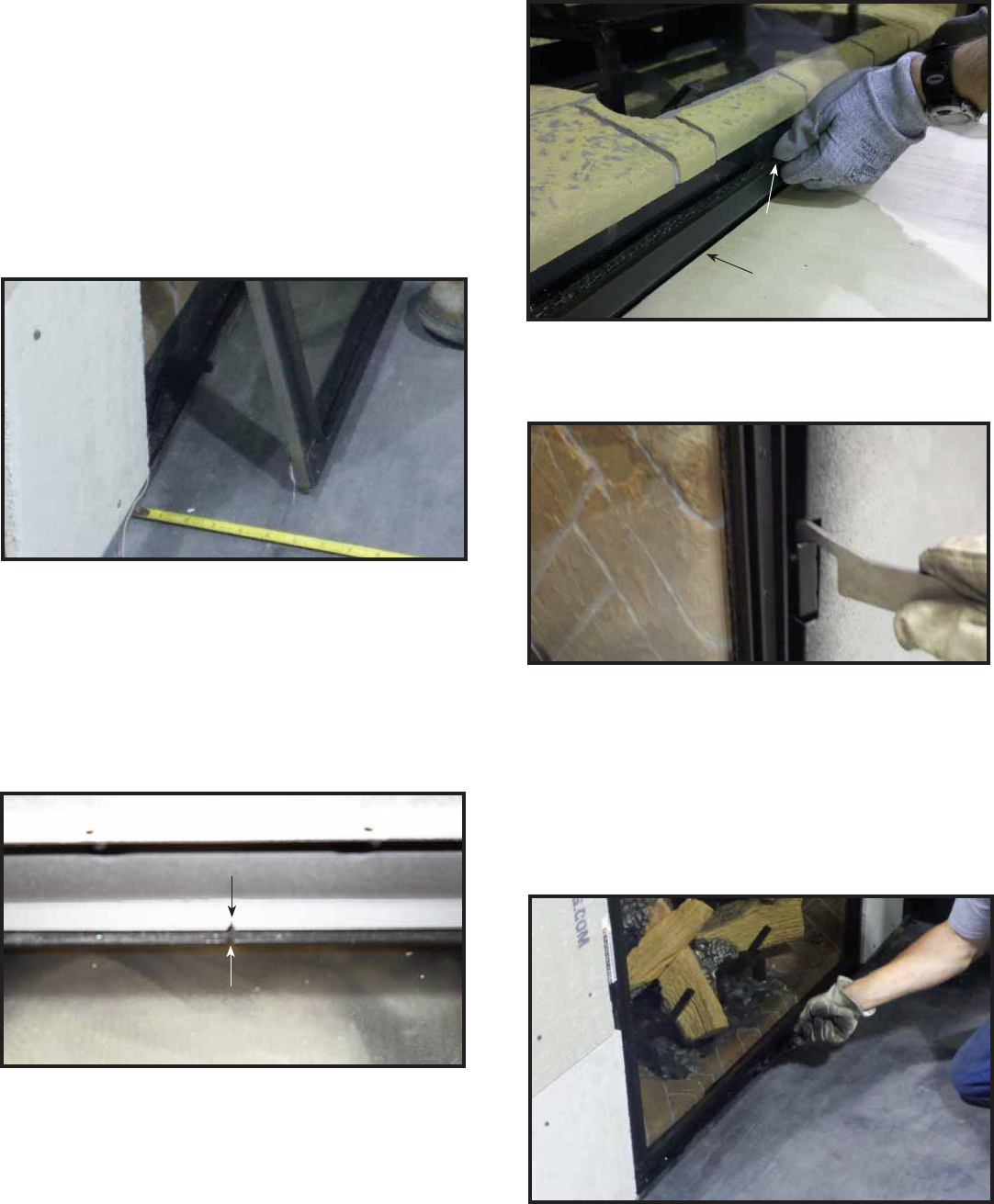
TOP RETAINING RAIL NOTCH
TOP RETAINING RAIL NOTCH
GLASS FRAME NOTCH
GLASS FRAME NOTCH
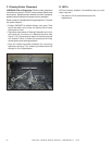
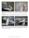
Figure 14.9 Positioning Glass
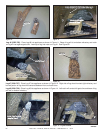
Figure 14.11. Installing Glass
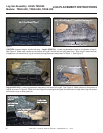
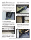
Replacing Fixed Glass Assembly
This fi xed glass assembly is held in place by two side
clips, one top retaining rail and lower glass clips. The
TRUE36 has three lower glass clips and the TRUE42 and
TRUE50 have four lower glass clips. To remove clips, en-
gage the spring clips with the tool and pull tool out slightly.
Rotate wrist left and right to disengage clip. The glass clip
tool is shown in Figure 14.6.
1. Tool is fastened to the lower right corner of the fi re-
place. Remove tool by removing one screw. If glass
clip removal tool becomes misplaced, a cotter pin re-
moval tool may be used.
2. Position the fi xed glass assembly so that it is about
eight inches from the face of the appliance. See Fig-
ure 14.9. An arch door application will require the
glass to be installed at a steeper angle.
3. Center the fi xed glass assembly from left to right in-
side the top of the appliance opening.
The glass frame has tabs on the bottom that coincide
with the bottom glass clip location. The TRUE-36 has
three tabs and the TRUE-42 and TRUE-50 have four
tabs. If the glass is not centered, it cannot be installed
properly. Align the notch at the top center of the glass
frame assembly with the notch on the top retaining
rail. See Figure 14.10.
Figure 14.10. Align Notches
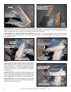
Figure 14.12. Securing Side Glass Clips
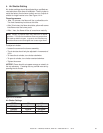
4. Install fi xed glass assembly by lifting it up and sliding
it into the top retaining rail. Grasp the fi xed glass as-
sembly on the sides.
CAUTION! Risk of Injury! DO NOT put fi ngers under
glass frame. Fingers may get pinched by glass frame
during installation.
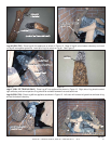
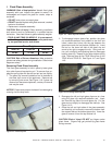
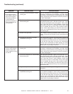
6. Once the left and right glass clips are installed, en-
gage the bottom clips by inserting the glass clip tool at
a sharp downward angle to get between the gap be-
tween the glass frame and the front bottom fi replace
lip. See Figure 14.13.
7. Return glass tool to its shipping location in the low-
er right corner of the appliance and secure with one
screw.
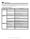
5. Ensure the fi xed glass assembly is situated tight
against the fi rebox face. Engage the left and right
glass clips using the glass clip tool. See Figure 14.12.
Figure 14.13. Securing Bottom Glass Clips
Once the glass is installed tightly into the top retainer
rail, push in the bottom so that the glass assembly
rests on the support tabs on the glass clip. See Fig-
ure 14.11.
GRASP FRAME BY LIP THAT
GRASP FRAME BY LIP THAT
PROJECTS FROM GLASS. DO NOT
PROJECTS FROM GLASS. DO NOT
INSERT FINGERS UNDER RAIL.
INSERT FINGERS UNDER RAIL.
RAIL
RAIL
LIP
LIP