


33
Heat & Glo •
TRUE-36, TRUE-42, TRUE-50 • 2282-900 Rev. D • 8/12
F. PVK-80 and PVI-SLP Information
This section provides specifi c detail for installation of
TRUE-36, TRUE-42, and TRUE-50 models with ap-
proved power vent kits. Follow instructions included with
the PVK-80 or PVI-SLP power vent kits.
See Table 7.1 below for approved Power Venting options
for TRUE models.
WARNING! Risk of Fire! Use ONLY Hearth & Home
Technologies-approved power venting systems with this
appliance. Use of power venting systems not approved
by Hearth & Home Technologies may cause fi replace to
overheat.
The power vent draft fl ow must be adjusted and set per
the specifi cations in Table 7.2. Refer to the instructions
provided with the PVK-80 and PVI-SLP for more specifi c
information.
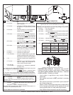
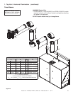
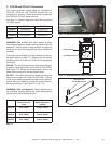
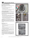
PVK-80: The exhaust control lever reduces the draft as it
is opened. Open the exhaust control lever to FULL OPEN.
See Figure 7.10. Secure the exhaust control lever to the
power vent housing with the sheet metal screw.
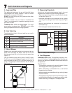
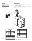
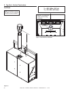
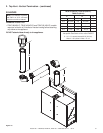
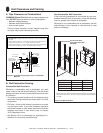
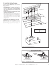
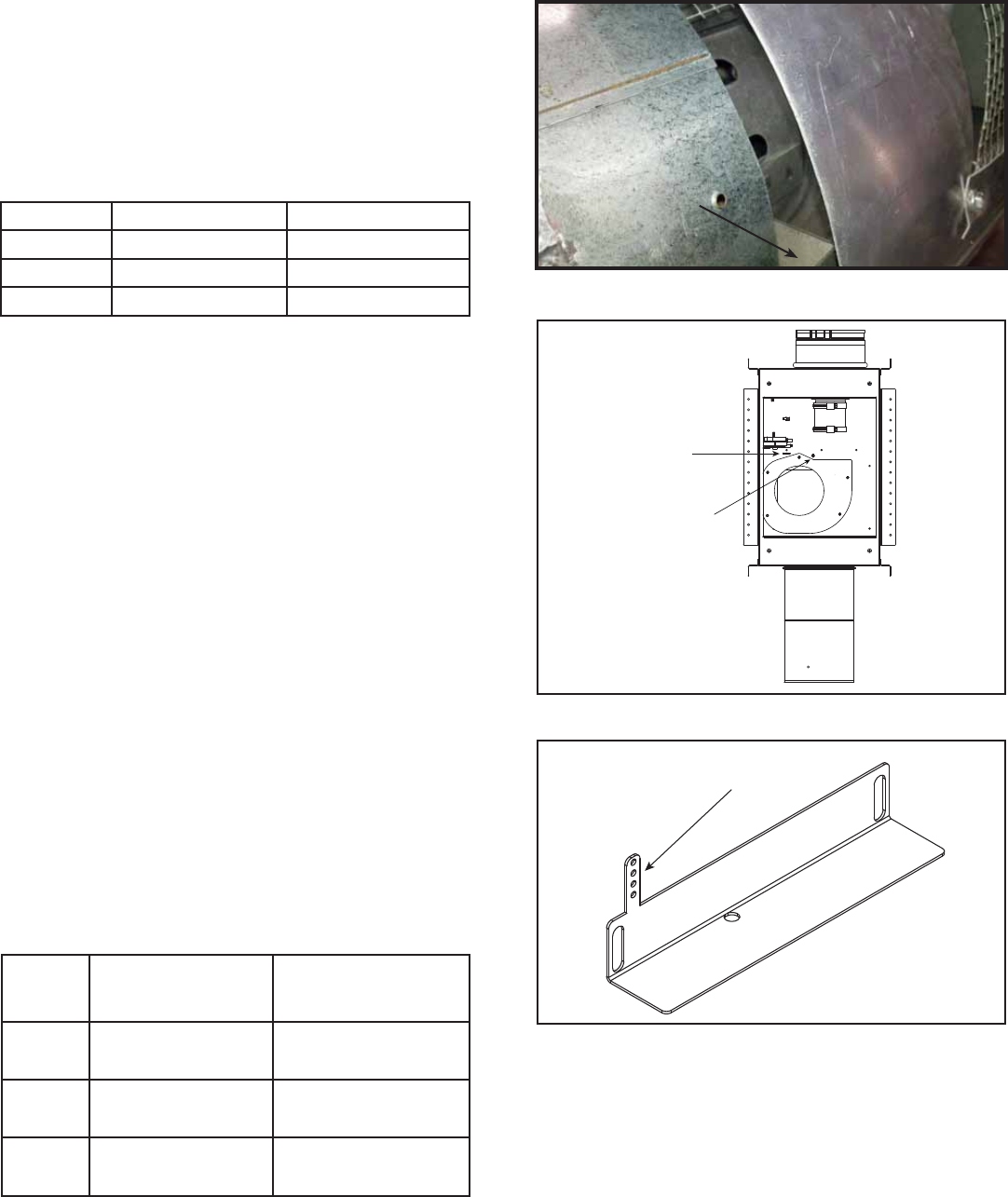
PVI-SLP: The baffl e adjustment is measured using the
holes on the indicator bar of the PVI-SLP baffl e. This bar
raises as the baffl e is opened and lowers as the baffl e is
closed. Adjust the baffl e by turning the screw located in
the motor enclosure. See Figure 7.11 and 7.12.
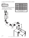
PVK-80
Exhaust Control
Lever
PVI-SLP
Baffl e Adjustment
Setting
TRUE-36 FULL OPEN 3 Holes Visible
TRUE-42 FULL OPEN 3 Holes Visible
TRUE-50 FULL OPEN 3 Holes Visible
Table 7.2
Figure 7.11 Baffl e Adjustment Location - PVI-SLP
ADJUSTMENT BOLT
INDICATOR BAR
INDICATOR BAR
ADJUSTMENT HOLES
Figure 7.12 Baffl e Adjustment - PVI-SLP
Figure 7.10 PVK-80 Control Lever Adjustment - Open
Table 7.1
WARNING! Risk of Explosion! Follow instructions to
set draft fl ow. Incorrect setting may impair burner perfor-
mance and/or cause delayed ignition.
EXHAUST CONTROL LEVER
EXHAUST CONTROL LEVER
PVK-80 PVI-SLP
TRUE-36 APPROVED APPROVED
TRUE-42 APPROVED APPROVED
TRUE-50 APPROVED APPROVED